Calculate Voltage Regulation of Distribution Line
May 12, 2013 14 Comments
Introduction:
- Voltage regulation or Load Reguation is to maintain a fixed voltage under different load.Voltage regulation is limiting factor to decide the size of either conductor or type of insulation.
- In circuit current need to be lower than this in order to keep the voltage drop within permissible values. The high voltage circuit should be carried as far as possible so that the secondary circuit have small voltage drop.
Voltage Regulation for 11KV, 22KV, 33KV Overhead Line (As per REC):
-
% Voltage Regulation= (1.06xPxLxPF) / (LDFxRCxDF)
- Where
- P=Total Power in KVA
- L= Total Length of Line from Power Sending to Power Receiving in KM.
- PF= Power Factor in p.u
- RC= Regulation Constant (KVA-KM) per 1% drop.
- RC=(KVxKVx10)/( RCosΦ+XSinΦ)
- LDF= Load Distribution Factor.
- LDF= 2 for uniformly distributed Load on Feeder.
- LDF>2 If Load is skewed toward the Power Transformer.
- LDF= 1 To 2 If Load is skewed toward the Tail end of Feeder.
- DF= Diversity Factor in p.u
Permissible Voltage Regulation (As per REC):
|
Maximum Voltage Regulation at any Point of Distribution Line |
|||
| Part of Distribution System | Urban Area (%) | Suburban Area (%) | Rural Area (%) |
| Up to Transformer | 2.5 | 2.5 | 2.5 |
| Up to Secondary Main | 3 | 2 | 0.0 |
| Up to Service Drop | 0.5 | 0.5 | 0.5 |
| Total | 6.0 | 5.0 | 3.0 |
Voltage Regulation Values:
- The voltage variations in 33 kV and 11kV feeders should not exceed the following limits at the farthest end under peak load conditions and normal system operation regime.
- Above 33kV (-) 12.5% to (+) 10%.
- Up to 33kV (-)9.0% to (+)6.0%.
- Low voltage (-)6.0% to (+) 6.0%
- In case it is difficult to achieve the desired voltage especially in Rural areas, then 11/0.433kV distribution transformers(in place of normal 11/0.4kV DT’s) may be used in these areas.
Required Size of Capacitor:
- Size of capacitor for improvement of the Power Factor from Cos ø1 to Cos ø2 is
-
Required size of Capacitor(Kvar) = KVA1 (Sin ø1 – [Cos ø1 / Cos ø2] x Sin ø2)
- Where KVA1 is Original KVA.
Optimum location of capacitors:
-
L = [1 – (KVARC / 2 KVARL) x (2n-1)]
- Where,
- L = distance in per unit along the line from sub-station.
- KVARC = Size of capacitor bank
- KVARL = KVAR loading of line
- n = relative position of capacitor bank along the feeder from sub-station if the total capacitance is to be divided into more than one Bank along the line. If all capacitance is put in one Bank than values of n=1.
Voltage Rise due to Capacitor installation:
-
% Voltage Rise = (KVAR(Cap)x Lx X) / 10xVx2
- Where,
- KVAR(Cap)=Capacitor KVAR
- X = Reactance per phase
- L=Length of Line (mile)
- V = Phase to phase voltage in kilovolts
Calculate % Voltage Regulation of Distribution Line :
- Calculate Voltage drop and % Voltage Regulation at Trail end of following 11 KV Distribution system , System have ACSR DOG Conductor (AI 6/4.72, GI7/1.57),Current Capacity of ACSR Conductor =205Amp,Resistance =0.2792Ω and Reactance =0 Ω, Permissible limit of % Voltage Regulation at Trail end is 5%.
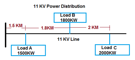
Method-1 (Distance Base):
-
Voltage Drop = ( (√3x(RCosΦ+XSinΦ)x I ) / (No of Conductor/Phase x1000))x Length of Line
Voltage drop at Load A
- Load Current at Point A (I) = KW / 1.732xVoltxP.F
- Load Current at Point A (I) =1500 / 1.732x11000x0.8 = 98 Amp.
- Required No of conductor / Phase =98 / 205 =0.47 Amp =1 No
- Voltage Drop at Point A = ( (√3x(RCosΦ+XSinΦ)xI ) / (No of Conductor/Phase x1000))x Length of Line
- Voltage Drop at Point A =((1.732x (0.272×0.8+0x0.6)x98) / 1×1000)x1500) = 57 Volt
- Receiving end Voltage at Point A = Sending end Volt-Voltage Drop= (1100-57) = 10943 Volt.
- % Voltage Regulation at Point A = ((Sending end Volt-Receiving end Volt) / Receiving end Volt) x100
- % Voltage Regulation at Point A = ((11000-10943) / 10943 )x100 = 0.52%
- % Voltage Regulation at Point A =0.52 %
Voltage drop at Load B
- Load Current at Point B (I) = KW / 1.732xVoltxP.F
- Load Current at Point B (I) =1800 / 1.732x11000x0.8 = 118 Amp.
- Distance from source= 1500+1800=3300 Meter.
- Voltage Drop at Point B = ( (√3x(RCosΦ+XSinΦ)xI ) / (No of Conductor/Phase x1000))x Length of Line
- Voltage Drop at Point B =((1.732x (0.272×0.8+0x0.6)x98) / 1×1000)x3300) = 266 Volt
- Receiving end Voltage at Point B = Sending end Volt-Voltage Drop= (1100-266) = 10734 Volt.
- % Voltage Regulation at Point B= ((Sending end Volt-Receiving end Volt) / Receiving end Volt) x100
- % Voltage Regulation at Point B= ((11000-10734) / 10734 )x100 = 2.48%
- % Voltage Regulation at Point B =2.48 %
Voltage drop at Load C
- Load Current at Point C (I) = KW / 1.732xVoltxP.F
- Load Current at Point C (I) =2000 / 1.732x11000x0.8 = 131 Amp
- Distance from source= 1500+1800+2000=5300 Meter.
- Voltage Drop at Point C = ( (√3x(RCosΦ+XSinΦ)xI ) / (No of Conductor/Phase x1000))x Length of Line
- Voltage Drop at Point C =((1.732x (0.272×0.8+0x0.6)x98) / 1×1000)x5300) = 269 Volt
- Receiving end Voltage at Point C = Sending end Volt-Voltage Drop= (1100-269) = 10731 Volt.
- % Voltage Regulation at Point C= ((Sending end Volt-Receiving end Volt) / Receiving end Volt) x100
- % Voltage Regulation at Point C= ((11000-10731) / 10731 )x100 = 2.51%
- % Voltage Regulation at Point C =2.51 %
Here Trail end Point % Voltage Regulation is 2.51% which is in permissible limit.
Method-2 (Load Base):
-
% Voltage Regulation =(I x (RcosǾ+XsinǾ)x Length ) / No of Cond.per Phase xV (P-N))x100
Voltage drop at Load A
- Load Current at Point A (I) = KW / 1.732xVoltxP.F
- Load Current at Point A (I) =1500 / 1.732x11000x0.8 = 98 Amp.
- Distance from source= 1.500 Km.
- Required No of conductor / Phase =98 / 205 =0.47 Amp =1 No
- Voltage Drop at Point A = (I x (RcosǾ+XsinǾ)x Length ) / V (Phase-Neutral))x100
- Voltage Drop at Point A =((98x(0.272×0.8+0x0.6)x1.5) / 1×6351) = 0.52%
- % Voltage Regulation at Point A =0.52 %
Voltage drop at Load B
- Load Current at Point B (I) = KW / 1.732xVoltxP.F
- Load Current at Point B (I) =1800 / 1.732x11000x0.8 = 118 Amp.
- Distance from source= 1500+1800=3.3Km.
- Required No of conductor / Phase =118 / 205 =0.57 Amp =1 No
- Voltage Drop at Point B = (I x (RcosǾ+XsinǾ)x Length ) / V (Phase-Neutral))x100
- Voltage Drop at Point B =((118x(0.272×0.8+0x0.6)x3.3)/1×6351) = 1.36%
- % Voltage Regulation at Point A =1.36 %
Voltage drop at Load C
- Load Current at Point C (I) = KW / 1.732xVoltxP.F
- Load Current at Point C (I) =2000 / 1.732x11000x0.8 = 131Amp.
- Distance from source= 1500+1800+2000=5.3Km.
- Required No of conductor / Phase =131/205 =0.64 Amp =1 No
- Voltage Drop at Point C = (I x (RcosǾ+XsinǾ)x Length ) / V (Phase-Neutral))x100
- Voltage Drop at Point C =((131x(0.272×0.8+0x0.6)x5.3)/1×6351) = 2.44%
- % Voltage Regulation at Point A =2.44 %
Here Trail end Point % Voltage Regulation is 2.44% which is in permissible limit.
 JIGNESH PARMAR





Dear Sir,Can you help me.I have 3 phase line each line have current transformer,we know that current transformer have polarity.we have ( + ) and ( -) sign.Positive sign direct to the ammeter,and the negative can i put direct to the ammeter or can i put by series? Please help me, Regadrs, Angelito Cortez
Dear sir, I m a recent passout and working in a electrical design firm, our all experienced persons has resigned and I m facing problem in calculating size and rating of ctpt, vcb,control panel, relay,cable calculation for substation and switch yard. I need your help on these topics. Pls help me out. Thanks in advance. Best Regds, Chhavi
Is there a ” Buy Unlocked version” available
padlock01
I am electrician just start out I need some help
hello sir,
thanks for ur site.Iam from Andhrapradesh working as assistant engineer for commercial section where we have to draw 11kv sketches and LT sketches and estimate quantity of matieral required for that particular work.But it was very new to me.Idon’t know how to check the sketches send by the field engineers for their works like DTR erection,service line erection and shifting of poles,providing DP structures etc.please give me some tips so that i can enhance my knowledge in my work.
My dear Mr Parmer ,
I am working on a project in Rajasthan where 11KV/0.433KV , three phase three wire system is being used . Whereever 230 V supply is required for Power and lighting , they are using 440V/ 230V lighting transformers . The lighting transformers are provided with earth and it is earthed .The client wants me to follow the same system even though I am not convinced to follow the same system. As the unit is connected with oil and gas plants , they want to use CBCT,RCBO,ELCB etc to the great extent . Please study and give your observations on the existing system.
H.SATHIAMOORTHY
Hi,
i want to know for the protection of equipment and tower in communication which lightening protection method is better. Lightening rod connected to bonding of body earthing or separate lightening earthing and separate for body earthing.
I want regulation constant table for various types of conductor
sir how to calculate VR of composite conductor i.e UG Cable and OH line
who many voltage drop of Dog ACSR conductor as per kv/as per km on 11000 a.c crunnt
How can I calculate HT line voltage drop for CU/XLPE/ PVC cable in trench.
Please give me suggestion. I hope I will get one advice from you.
What is the rupees per MW.km value for 11 kV lines and for 33 kv lines?
Dear sir,
i hope you are healthy, can you tell me, in voltage drop calculation for all three point (A,B and C) you considered the load current the same 98A, but in point B the load current is 118A and in point C the load current is 131A
Respected sir i need to know calculation of LTVR in 440v, 4 wire system.