Method for Installation of Conceal & Surface Conduits (Part-2)
September 18, 2021 1 Comment
4.Filling Chasing Area:
- All grooves, chases shall be properly filled and concreted and finished up to the wall surface before plastering of walls is taken up. The conduit boxes, accessories, joints, etc. shall be laid along with the conduits. The chases shall be sufficiently deep and properly filled with cement mortar.
- Where conduits pass through expansion joints in the building, adequate expansion fittings or other approved services shall be used to take care of any relative movement. As far as possible, chasing of wall to embed the conduits to be avoided.
- Chasing is filled by Cement mortar 1:5 ratio(1 portion of the cement+5 portion of sand) shall be used for patchwork in chased area and its surface is rough so main plaster will easily joint on chasing area.
- Curing shall be carried out for a minimum of three days.
- Make sure the conduits are not visible from outside their route which could lead to improper plastering.
5.Wire Mesh:
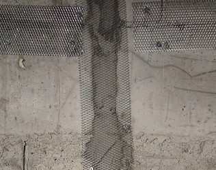
- After chasing area is filled by mortar, Chicken (wire) mesh and GI nails shall be applied on chasing area to avoid hair crack in plaster.
- Width of Chicken Mesh is slightly larger than chasing Area. After installation of Chicken mesh final Plaster should be done.
- Make Sure that Nails for Wire Mesh should not damage the Buried PVC Conduit.
6.Surface Conducting:.
- Take the approved Drawings of Electrical conduit Shop Drawing with section details, MEP coordination drawing with section details and Architectural Drawings.
- Ensure that the civil people have finished block wall and Plastering with adequate curing and clearance is given to proceed for electrical works.
- Check the required reference markings are available for FFL (finished floor levels).
- All required materials shall be shifted and stored under safe custody near workplace on daily basis as per planned quantity.
1 ) Marking of Conduits:
- Site Engineer will carry out a site survey where the PVC Conduit will be installed as per approved shop drawings.
- Mark the exact position of the conduit route with the blue marker string and then install conduit saddles.
- All runs must be installed as a complete system before any conductors are pulled into them. In other words, a run of conduit (to include conduit, fittings, and supports) must be complete before the conductors are installed.
- A run of conduit should be as straight and direct as possible. When a number of conduit runs are to be installed parallel and next to each other, install them all at the same time.
2) Installation of Conduits:
(A) PVC Conduit and Accessories:
- Conduits shall run vertically or horizontally only for surfaced run conduits.
- Install the correct Type and size of the conduits as per approved Specification and drawing.
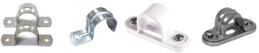
- Conduit pipes shall be fixed by heavy gauge saddles, secured to suitable wood plugs or other approved plugs with screws in an approved manner at an interval of not more than 1 meter but on either side of the couplers or bends or similar fittings, saddles shall be fixed at a distance of 30cm from the center of such fittings.
- The saddles should not be less than 19MM (width) of 24 gauge for conduits up to 25 mm dia and not less than 25mm (width) of 20 gauge for larger diameter conduits.
- Where conduit pipes are to be laid along the trusses, steel joint etc. the same shall be secured by means of special clamps made of MS. Where as it is not possible to drill holes in the trusses members suitable clamps with bolts and nuts shall be used.
- Where conduit pipes are to be laid above false ceiling, either conduit pipes shall be clamp to false ceiling frame work or suspended with suitable supports from the ceiling slab.
- For conduit pipe run along with wall, the conduit pipe shall be clamped to wall above false ceiling in uniform pattern with special clamps if required to be approved by the Engineer-In-Charge at site.
- Check to ensure no sharp edges within the conduit joints for surfaced conduit and to ensure proper bonding for all conduit joint for concealed PVC conduit by foreman / skill worker / sub-contractor.
- All joints in PVC conduits, other than screwed joints, shall be cemented with a waterproof adhesive. This adhesive shall be as recommended by the conduit manufacturer.
- All saddles, tubes and boxes must be in perfect alignment to avoid any appearance of warping when the installation is complete. Saddles should not be so tight as to prevent expansion of the conduit.
- Power conduit and LV conduit need to be separate. Power, Lighting Circuit should be run in separate conduit than LV circuit (Data wire, Telephone wire, TV wire) conduit.
- Conduits shall not be run closer than 15m to any steam or hot water pipes and shall be run underneath such pipes rather than over them.
- Conduits should not also be run closer than 05m to any telephone, bell or other signaling circuit.
- Particular care shall be taken to ensure that no grout or other foreign materials enters the conduit system through joints, or through surface openings.
- All conduits shall be run as far as possible along the walls and ceiling and above false ceilings so as to be easily accessible for inspection if need be. While the Architects drawings indicate the distribution for light and power points
- PVC conduits shall be ISI grade and it shall be rigid type. Where conduits are laid in straight run, draw boxes shall be provided at intervals not exceeding 10 meters. Between two consecutive draw boxes the right angle bends shall not exceed two in number.
- Drawn-in boxes must be provided to give access to all conduit for the drawing-in or out of any cable after the installation is completed.
- Terminations of PVC conduits into switch boxes, DBs, etc. shall be with adapters. PVC conduits shall be fixed to accessories such as coupler, circular boxes, etc. with vinyl cement.
(B) GI / Steel Conduit and Accessories:
- GI Conduiting layout complete with MEP coordination and Architectural Drawing complete with section details.
- Check the route of GI Conduiting free from debris and no obstruction of any other activity.
- Arrange scaffolding of sufficient height approved by HSE officer.
- Mark the reference points on wall/ column as per civil architectural drawing.
- Identify the circuit start point and end & mark GI Conduiting route as per approved drawings.
- Prior to erection, all burrs and sharp edges shall be removed from the conduit together with any dirt, oil or paint which may be present.
- Standard length of conduits shall be cut to the required length.
- For GI Conduits threading shall be done using a threading tools and appropriate die-set. Thread will be kept to a minimum from coupling and boxes. Zink rich paint to be applied to the exposed thread part of GI conduit.
- Where required conduits shall be bent to the required radius using manual bending machines.
- Conduits are fixed to the building fabric by means of distance saddle with appropriate metal screws will be allowed.
- Spacer bar are fixed in regular interval not exceeding 1000mm and the distance from either side of ay box or bend to the nearest spacer bar shall not be more than 150mm.
- All terminal boxes area marked on the appropriate location (wall/ceiling) as per approved shop drawing and fixed with metal screws and plug. Suitable bushes are used where conduit enters the boxes to avoid any damage to the wires.
- Wherever necessary ropes shall be pulled into conduit runs ending and kept at pull boxes for the future purpose. Ensure that sufficient number of pull boxes is installed.
- Metallic conduit boxes shall be sued throughout metallic conduit raceway system.
- GI flexible conduits shall be used to make connections from un-accessible location and end connections to terminal boxes.
- All pull boxes, junction boxes fixed on the wall in the route of steel conduit shall be provided with GI cover after pulling the wires.
- Steel conduiting shall be conforming to relevant IS specifications (IS 9537). All steel conduits shall be of heavy gauge, welded and threaded type. Conduit accessories such as boxes, bends, inspection bends, boxes, elbows, reducers, etc. shall conform to relevant standards. As far as possible, boxes shall have internally tapped spouts to receive the conduits.
- Where conduits are installed in straight run, draw boxes shall be provided at intervals not exceeding 30 feet (9 meters). Between two consecutive draw boxes, the right angle bends shall not exceed two in number. Conduits shall be properly threaded and screwed in to the accessories.
- The minimum size of conduits used shall be 20 mm. The minimum thickness of the conduits shall be 16 SWG.
- Wherever steel conduits terminate into points control boxes, distribution boards, etc. conduits shall be rigidly connected to the boxes, boards, etc. with check nuts on either side of the entry to ensure electrical continuity and with PVC or Bakelite bushes. Turning joints in conduits wherever necessary shall be rigidly held in aligned position by check nut tightened on the running side.
- After conduits, junction boxes, outlets, etc. are fixed in position, their outlets shall be properly plugged with PVC stop cover or with any other suitable material so that water, mortar, vermin or any other foreign material do not enter into the conduit system.
| Maximum number of PVC insulated 650/1100 V Copper conductor cable conforming to IS: 694-1990 | ||||||||||
| Conduit size | 20mm | 25mm | 32mm | 40mm | 50mm | |||||
| Wire Size (Sq.mm) | S | B | S | B | S | B | S | B | S | B |
| 1.5 Sq.mm | 7 | 5 | 12 | 10 | 20 | 14 | – | – | – | – |
| 2.5 Sq.mm | 6 | 5 | 10 | 8 | 18 | 12 | – | – | – | – |
| 4 Sq.mm | 4 | 3 | 7 | 6 | 12 | 10 | – | – | – | – |
| 5 Sq.mm | 3 | 2 | 6 | 5 | 10 | 8 | – | – | – | – |
| 10 Sq.mm | 2 | – | 4 | 3 | 6 | 5 | 8 | 6 | – | – |
| 16 Sq.mm | – | – | 2 | – | 4 | 3 | 7 | 6 | – | – |
| 25 Sq.mm | – | – | – | – | 3 | 2 | 5 | 4 | 8 | 6 |
| The columns heads ‘S’ apply to runs of conduits which have distance not exceeding 4.25 m between draw in boxes and which do not deflect from the straight by an angle of more than 15 degrees. | ||||||||||
| The columns heads ‘B’ apply to runs of conduit which deflect from the straight by an angle of more than 15 degrees. | ||||||||||
Bending of Conduit:
- It may be necessary to create bends in the field by heating and deforming rigid conduit.
- For heating the rigid conduit, use a heat gun or some other flameless heat source. Do not use an open flame to heat the conduit. The rigid conduit must be heated to approximately 125˚C in order to bend without kinking.
- Heat a length of conduit equal to approximately 10 times the rigid conduit nominal diameter.
- Once the rigid conduit has been adequately heated, bend it to the required angle plus 3 extra degrees. The additional angle will accommodate the “spring back” which will occur during cooling.
- After bending of the conduit is completed, immediately cool the bend using water or cold air.
| Conduit Bending Radius | |
| Size of Conduit | Radius to Center of Conduit |
| 12 mm | 100 mm |
| 20 mm | 112 mm |
| 25 mm | 144.8 mm |
| 30 mm | 183.9 mm |
| 40mm | 208 mm |
| 50 mm | 238 mm |
| 63 mm | 266 mm |
| 75 mm | 330 mm |
| 88 mm | 370 mm |
| 100 mm | 403 mm |
| 127 mm | 609 mm |
| 152 mm | 762 mm |
REFERENCES:.
- IS 3854 1966: Switches for domestic and similar purpose.
- IS 1293 1967: Three pin plug and socket outlets.
- IS 4614 1968: Switch Socket outlet (non-interlocking type)
- IS 6538 1971: Three pin plugs made of resistant materials.
- IS 9537-3 (1983): Rigid plain conduits of insulating materials.
- IS 3419 (1989): Fittings rigid non-metallic conduits
 JIGNESH PARMAR



Recent Comments