Short Circuit Current Calculation (Base KVA Method)
September 9, 2014 79 Comments
Example:
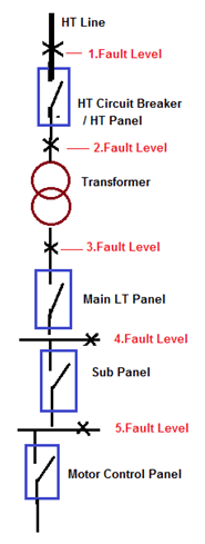
Calculate Fault current at each stage of following Electrical System SLD having details of.
- Main Incoming HT Supply Voltage is 6.6 KV.
- Fault Level at HT Incoming Power Supply is 360 MVA.
- Transformer Rating is 2.5 MVA.
- Transformer Impedance is 6%.
 Calculation:
- Let’s first consider Base KVA and KV for HT and LT Side.
- Base KVA for HT side (H.T. Breaker and Transformer Primary) is 6 MVA
- Base KV for HT side (H.T. Breaker and Transformer Primary) is 6.6 KV
- Base KVA for LT side (Transformer Secondary and down Stream) is 2.5 MVA
- Base KV for LT side (Transformer Secondary and down Stream) is 415V
Fault Level at HT Side (Up to Sub-station):
(1) Fault Level from HT incoming Line to HT Circuit Breaker
- HT Cable used from HT incoming to HT Circuit Breaker is 5 Runs , 50 Meter ,6.6KV 3 Core 400 sq.mm Aluminum Cable , Resistance of Cable 0.1230 Ω/Km and Reactance of Cable is0.0990 Ω/Km.
- Total Cable Resistance(R)= (Length of Cable X Resistance of Cable) / No of Cable.
- Total Cable Resistance=(0.05X0.1230) / 5
- Total Cable Resistance=0.001023 Ω
- Total Cable Reactance(X)= (Length of Cable X Reactance of Cable) / No of Cable.
- Total Cable Reactance=(0.05X0.0990) / 5
- Total Cable Reactance =0.00099 Ω
- Total Cable Impedance (Zc1)=√(RXR)+(XxX)
- Total Cable Impedance (Zc1)=0.0014235 Ω——–(1)
- U Reactance at H.T. Breaker Incoming Terminals (X Pu)= Fault Level / Base KVA
- U Reactance at H.T. Breaker Incoming Terminals (X Pu)= 360 / 6
- U. Reactance at H.T. Breaker Incoming Terminals(X Pu)= 0.01666 PU——(2)
- Total Impedance up to HT Circuit Breaker (Z Pu-a)= (Zc1)+ (X Pu) =(1)+(2)
- Total Impedance up to HT Circuit Breaker(Z Pu-a)=0.001435+0.01666
- Total Impedance up to HT Circuit Breaker (Z Pu-a)=0.0181 Ω.——(3)
- Fault MVA at HT Circuit Breaker= Base MVA / Z Pu-a.
- Fault MVA at HT Circuit Breaker= 6 / 0.0181
- Fault MVA at HT Circuit Breaker= 332 MVA
- Fault Current = Fault MVA / Base KV
- Fault Current = 332 / 6.6
- Fault Current at HT Circuit Breaker = 50 KA
(2) Fault Level from HT Circuit Breaker to Primary Side of Transformer
- HT Cable used from HT Circuit Breaker to Transformer is 3 Runs , 400 Meter ,6.6KV 3 Core 400 sq.mm Aluminium Cable , Resistance of Cable 0.1230 Ω/Km and Reactance of Cable is0.0990 Ω/Km.
- Total Cable Resistance(R)= (Length of Cable X Resistance of Cable) / No of Cable.
- Total Cable Resistance=(0.4X0.1230) / 3
- Total Cable Resistance=0.01364 Ω
- Total Cable Reactance(X)= (Length of Cable X Reactance of Cable) / No of Cable.
- Total Cable Reactance=(0.4X0.0990) / 5
- Total Cable Reactance =0.01320 Ω
- Total Cable Impedance (Zc2)=√(RXR)+(XxX)
- Total Cable Impedance (Zc2)=0.01898 Ω——–(4)
- U Impedance at Primary side of Transformer (Z Pu)= (Zc2 X Base KVA) / (Base KV x Base KVx1000)
- U Impedance at Primary side of Transformer (Z Pu)= (0.01898X6) /(6.6×6.6×1000)
- U Impedance at Primary side of Transformer (Z Pu)= 0.0026145 PU——(5)
- Total Impedance(Z Pu)=(4) + (5)
- Total Impedance(Z Pu)=0.01898+0.0026145
- Total Impedance(Z Pu)=0.00261——(6)
- Total Impedance up to Primary side of Transformer (Z Pu-b)= (Z Pu)+(Z Pu-a) =(6)+(3)
- Total Impedance up to Primary side of Transformer (Z Pu-b)= 0.00261+0.0181
- Total Impedance up to Primary side of Transformer (Z Pu-b)=0.02070 Ω.—–(7)
- Fault MVA at Primary side of Transformer = Base MVA / Z Pu-b.
- Fault MVA at Primary side of Transformer = 6 / 0.02070
- Fault MVA at Primary side of Transformer = 290 MVA
- Fault Current = Fault MVA / Base KV
- Fault Current = 290 / 6.6
- Fault Current at Primary side of Transformer = 44 KA
(3) Fault Level from Primary Side of Transformer to Secondary side of Transformer:
- Transformer Rating is 2.5 MVA and Transformer Impedance is 6%.
- % Reactance at Base KVA = (Base KVA x % impedance at Rated KVA) / Rated KVA
- % Reactance at Base KVA = (2.5X6)/2.5
- % Reactance at Base KVA =6%
- U. Reactance of the Transformer(Z Pu) =% Reactance /100
- U. Reactance of the Transformer(Z Pu)= 6/100=0.06 Ω—–(8)
- Total P.U. impedance up to Transformer Secondary Winding(Z Pu-c)=(Z Pu)+(Z Pu-b)=(7)+(8)
- Total P.U. impedance up to Transformer Secondary Winding(Z Pu-c)=0.06+0.02070
- Total P.U. impedance up to Transformer Secondary Winding(Z Pu-c)=0.0807 Ω—–(9)
- Fault MVA at Transformer Secondary Winding = Base MVA / Z Pu-c
- Fault MVA at Transformer Secondary Winding = 2.5/0.0807
- Fault MVA at Transformer Secondary Winding =31 MVA
- Fault Current = Fault MVA / Base KV
- Fault Current = 31 / (1.732×0.415)
- Fault Current at Transformer Secondary Winding = 43 KA
Fault Level at LT Side (Sub-station to Down stream):
(4) Fault Level from Transformer Secondary to Main LT Panel
- LT Cable used from Transformer Secondary to Main LT Panel is 13 Runs , 12 Meter , 1KV, 3.5C x 400 Sq.mm Aluminium Cable , Resistance of Cable 0.1230 Ω/Km and Reactance of Cable is0.0618 Ω/Km.
- Total Cable Resistance(R)= (Length of Cable X Resistance of Cable) / No of Cable.
- Total Cable Resistance=(0.012X0.1230) / 13
- Total Cable Resistance=0.00009 Ω
- Total Cable Reactance(X)= (Length of Cable X Reactance of Cable) / No of Cable.
- Total Cable Reactance=(0.012X0.0618) / 13
- Total Cable Reactance =0.00006 Ω
- Total Cable Impedance (Zc3)=√(RXR)+(XxX)
- Total Cable Impedance (Zc3)=0.00011 Ω——–(10)
- U Impedance at Main LT Panel (Z Pu)= (Zc3 X Base KVA) / (Base KV x Base KVx1000)
- U Impedance at Main LT Panel (Z Pu)= (0.00011X2.5×1000)/(0.415×0.415X1000)
- P P.U Impedance at Main LT Panel (Z Pu)= 001601 Ω ——(11)
- Total Impedance up to Main LT Panel (Z Pu-d)= (Zc3)+ (Z Pu-c) =(11)+(9)
- Total Impedance up to Main LT Panel (Z Pu-d)= 0.001601 +0.0807
- Total Impedance up to Main LT Panel (Z Pu-d)=0.082306 Ω.——(12)
- Fault MVA at Main LT Panel = Base MVA / Z Pu-a.
- Fault MVA at Main LT Panel = 2.5 / 0.082306
- Fault MVA at Main LT Panel = 30 MVA
- Fault Current = Fault MVA / Base KV
- Fault Current = 30 / (1.732X0.415)
- Fault Current at Main Lt Panel = 42 KA
(5) Fault Level from Main LT Panel to Sub Panel:
- LT Cable used from Main LT Panel to Sub Panel is 2 Runs , 160 Meter , 1KV, 3.5C x 400 Sq.mm Aluminium Cable , Resistance of Cable 0.1230 Ω/Km and Reactance of Cable is0.0618 Ω/Km.
- Total Cable Resistance(R)= (Length of Cable X Resistance of Cable) / No of Cable.
- Total Cable Resistance=(0.160X0.1230) / 2
- Total Cable Resistance=0.008184 Ω
- Total Cable Reactance(X)= (Length of Cable X Reactance of Cable) / No of Cable.
- Total Cable Reactance=(0.160X0.0618) / 2
- Total Cable Reactance =0.004944 Ω
- Total Cable Impedance (Zc4)=√(RXR)+(XxX)
- Total Cable Impedance (Zc4)=0.0095614 Ω——–(13)
- U Impedance at Sub Panel (Z Pu)= (Zc4 X Base KVA) / (Base KV x Base KVx1000)
- U Impedance at Sub Panel (Z Pu)= (0.0095614 X2.5×1000)/(0.415×0.415X1000)
- P P.U Impedance at Sub Panel (Z Pu)= 13879 Ω ——(14)
- Total Impedance up to Sub Panel (Z Pu-e)= (Zc4)+ (Z Pu-d) =(14)+(12)
- Total Impedance up to Sub Panel (Z Pu-e)= 0.13879 +0.082306
- Total Impedance up to Sub Panel (Z Pu-e)=0.2211 Ω.——(15)
- Fault MVA at Sub Panel = Base MVA / Z Pu-a.
- Fault MVA at Sub Panel = 2.5 / 0.2211
- Fault MVA at Sub Panel = 11 MVA
- Fault Current = Fault MVA / Base KV
- Fault Current = 11 / (1.732X0.415)
- Fault Current at Sub Panel = 16 KA
(6) Fault Level from Sub Panel to Motor Control Panel:
- LT Cable used from Sub Panel to Motor Control Panel is 6 Runs , 150 Meter , 1KV, 3.5C x 400 Sq.mm Aluminium Cable , Resistance of Cable 0.1230 Ω/Km and Reactance of Cable is0.0739 Ω/Km.
- Total Cable Resistance(R)= (Length of Cable X Resistance of Cable) / No of Cable.
- Total Cable Resistance=(0.150X0.1230) / 6
- Total Cable Resistance=0.003075 Ω
- Total Cable Reactance(X)= (Length of Cable X Reactance of Cable) / No of Cable.
- Total Cable Reactance=(0.150X0.0739) / 6
- Total Cable Reactance =0.0018475 Ω
- Total Cable Impedance (Zc5)=√(RXR)+(XxX)
- Total Cable Impedance (Zc4)=0.003587 Ω——–(16)
- U Impedance at Motor Control Panel (Z Pu)= (Zc5 X Base KVA) / (Base KV x Base KVx1000)
- U Impedance at Motor Control Panel (Z Pu)= (0.003587 X2.5×1000)/(0.415×0.415X1000)
- P P.U Impedance at Motor Control Panel (Z Pu)= 05207 Ω ——(17)
- Total Impedance up to Motor Control Panel (Z Pu-f)= (Zc5)+ (Z Pu-e) =(17)+(15)
- Total Impedance up to Motor Control Panel (Z Pu-e)= 0.13879 +0.2211
- Total Impedance up to Motor Control Panel (Z Pu-e)=0.27317 Ω.——(15)
- Fault MVA at Motor Control Panel = Base MVA / Z Pu-a.
- Fault MVA at Motor Control Panel = 2.5 / 0.27317
- Fault MVA at Motor Control Panel = 9 MVA
- Fault Current = Fault MVA / Base KV
- Fault Current = 9 / (1.732X0.415)
- Fault Current at Motor Control Panel = 13 KA
Summary of Calculation:
| Sr.No | Fault Location | Fault MVA | Fault Current (KA) |
|
1 |
At HT Circuit Breaker |
332 |
50 |
|
2 |
At Primary Side of Transformer |
290 |
44 |
|
3 |
At Secondary Side of Transformer |
31 |
43 |
|
4 |
At Main LT Panel |
30 |
42 |
|
5 |
At Sub Main Panel |
11 |
16 |
|
6 |
At Motor Control Panel |
9 |
13 |


really useful notes
Thank you sir
Good Morning,
Thank you for sharing valuable information.
Your explanation and simple and easy to understand,
Keep going…
Thanks & Regards,
BASKAR. C
Hello sir, Good morning. I have one doubt for fault current calculation. Please explain me what are the methods are available for caculate the fault current? Thsnks, palani from kolhapur india.
Sent from Samsung Mobile
Dear Parmer,
Kindly i would like to inform you there is a mistake in the calculation in the first one (1) Fault Level from HT incoming Line to HT Circuit Breaker which is hapened when you calculating the Resistance ( 0.05*0.1230)/5=0.00123 and this cause change in the total impedance and so on
thanks for your great effort.
wish u all the best
Dear Jignesh.Parmar thank you very much for sharing Nice article on Fault level calculations. Regards V V Joshi
Hello sir,
For a typical industrial power distribution system, which predominantly have induction motors, do we need to consider the motor contribution to the short circuit curents ? if yes then how do we do it ?
Regards,
Uday Kuamr
Dear Jignesh.Parmar thank you very much for sharing Nice article on Fault level calculations.
Regards,
shantan Mishra Bangalore.
Dear Sir Could you explane me from where we get 360/6=0.01666 u reactance at HT Breaker incoming terminal ,,and also please tell how to take Fault Level at HT Incoming Power Supply is 360 MVA please
Sir,how you calculate fault level at HT incoming side ie 360MVA
Hello please tell me how to calculate Earth fault current from Transformer to panel
Please help me that how Transformer impedance comes in picture to decide fault level on primary side of Transformer?
Sir, With due respect, I would like to say that In the above calculations Z(impedance of cable) having units in ohms is added to Z pu(of cable) having no units. I think that addition should be avoided in these calculations because only Zpu(upto that particular point) is the only parameter that should be used during every step of finding FAULT MVA. Also in a few areas(at HT SIDE particularly) 1.732 was missed. Thank You
Thank you for sharing your knowledge. Have you written books on Electrical Engineering?
dear sir,
how to calculate electrical clearance in substation
any formula pls send us sir
A 315kva 3phase has 120A, 115A and 130A. What is the total current and power
Dear Sir Could you explane me from where we get 360/6=0.01666 u reactants at HT Breaker incoming terminal (X Pu).
Dear Sir,
Could you explain that how to select base KVA for different KV levels
Jignesh sir, I am very thankful to you for providing a great material and educating all of us.
Sir I have a small doubt in short circuit current analysis.
Sir Why do we consider the same cable size(I.e.400 sq.mm aluminium) at all the sections( both H.T,L.T.) sides.
Please let me know my doubt sir thanking you…
Excellent
Jignesh Ji , well explained about short circuit calculations.
Dear Sir ,
How you considered –
Base KVA for HT side (H.T. Breaker and Transformer Primary) is 6 MVA
Plz tell me .
Thanks & Regards
Shiv
Dear Sir ,
If Transformer secondary to LT panel , we will use Bus bar than how to calculate Current / or as per above details consideration will be same . Plz reply my comments
Thanks
Shiv
Hi brother
Can you please show Method for calculate electric breaker both mono,three-phase use in hours or Apartment and give example.
Thank and best regard!
Silay
fine
sir, could you please how you are taken 360/6?
I would like to know the fault level will be given ?
What is U Reactance
You are sharing excellent knowledge it will help us to build our technical skill thanku
Thank you so much for such a wonderful explaination best i have ever seen
Dear Sir can you kindly explain me from where we get 360/6=0.01666 u reactants at HT Breaker incoming terminal (X Pu).
Great article. As an electrician I struggled with this for a long time. If you have an I Phone there is s great App called Transformer Pie that works out a trannies short circuit current for you. Maybe if use? Pongo
How MVA DIVIDED BY OHM CAN GIVE MVA again
Thank u a lot of for best explanation and make understand in better way. Thanks u so much again.
Hello sir, I have one doubt for cable short circuit calculation & lighting calculation. Please explain me what are the methods are available for caculate ? Thsnks,
Eng. Parmar, Sir, excellent example of fault calculation. One of the best I have come across. I have one question. How did you get the Base KVA as 6 MVA and should this not be base MVA. The transformer capacity is 2.5 MVA but the Base KVA is taken as 6 and I do not know from where this value was taken.
Kindly assist.
dear jignesh
there are some of mistake are there in calculation(not in procedure). some time not convert the impedences into per units.please rectify
Dear Sir Could you explane me from where we get 360/6=0.01666 u reactants at HT Breaker incoming terminal (X Pu).
and how base KVA is 6 MVA for incoming
Hi sir.
Fault Level at HT Incoming Power Supply is 360 MVA. how u taken that fault MVA?
hi am francisnkrumah from ghana and i want u to help me with some problem i need to meter a 2.5mva transformer with a ct panel i want to know what ct rating can be used for the 2.5mva hope to hear from u soon
H.T, What does this mean ? can you help me ? thank so much
I Just want to tell, the methods are very complicated and not understandable . How did you get this (Base KVA for HT side (H.T. Breaker and Transformer Primary) is 6 MVA) .
thanks sir
Thank u for ur information
Where did you get the information of reactance of the cable as well as the resistance of it?
Thanks
how to calculate LL, LG & LLG Fault current pls advice.
Good Morning,
Thank you for sharing valuable information.
Your explanation and simple and easy to understand,
Keep going…
Dear Sir,
In first step for (3)=(2)+(1)
In this 1 and 2 are in different units ,one is p.u another one is ohm how do you added this 2 different units, please explain Sir
Very easy to understand thank you
hello sir i have query how you considered base MVA for HT side .if you have any anther method for short ckt calculation .plz give me
I want to calculate the the GMR and GMD of under ground cable.Can you help me to find it with the help of an example.If you need I have the physical data also but i don’t know how to calculate it.
Dear sir, thankyou for the example. But I have a doubt, how did you consider the base MVA as 360 (fault level HT side) another boubt is how did you get the “Base KVA for HT side (H.T. Breaker and Transformer Primary) is 6 MVA”.
Kindly clarify my doubt.
how to find the fault level 360 at HT incoming power supply, pls answer
How did u assume that Base KVA is 6 MVA??
I am working in a RGGVY project. We are constructing 11kv new line using weasel conductors. While working on these lines we use discharge rods as safety measures. What current in the weasle conductors can cause the melting of the discharge rods cable which is a copper wire of 10 sq mm of length 13 mtrs.
As usual excellent explanation but what really irritates me is that calculation values are always wrong. It confuses your readers.
Dear sir
i want to know that we have use 630A VCB and Cable 30 Metter X-former Imp-5 and VCB set .8 how we will do calculate the Earthing rod /Cable please let me know
In the first calculation it should be baseKVA/MVA.
How to Calculate Fault level without Transformer ., It means If It is Feeder Protection how can i calculate the fault level..??
Thank
you sir
how to calculate faulat MVA for 20MVA transformer???
how to calculate Faulat MVA of 66KV/11KV ,20MVA transformer ..??
Dear sir,
Please clarify the asume base KVA for HT breaker,U reactance, PU .
U Reactance at H.T. Breaker Incoming Terminals (X Pu)= 360 / 6.
Please let me know where 360/6 comes from.
Good information very useful. Can you send me the pdf or word of the presentation or notes.
Sir, It’s really a good explaination..I have to asked how you select base MVA at HT side?
Great stuff
Thanks for this great sharing
could you explain how to calculate the incident Energy for Arc Flash
Thanks 🙏
Due to the fact that there are errors in your paper “Exaple: Short Circuit Current Calculation (kVA Method)”, kindly note that I am very much interested to know the answers to the comments of the readers of this paper.
Much obliged and many thanks
Please let me know the , how base KVA 6 come in point 1 and 2?
How can I understand base KVA in HT side?
Please shar eone calulation for effect of inductive Load current on Fault level also. It will be really helpful.
can anyone explain me how calculated base kva 6mva for ht side.
thank you very much for such detailed explanation hats off for your effort sir
What is meant by ( Base KVA of high tension side) please?
How can I get the calculation sheets please?
How do I calculate the system short circuit current when I have a 33kV/22kV step down transformer