Panel Design & Calculate Size of Bus bar
August 5, 2014 125 Comments
Example: Calculate Size of Bus bar having Following Details
- Bus bar Current Details:
- Rated Voltage = 415V,50Hz ,
- Desire Maximum Current Rating of Bus bar =630Amp.
- Fault Current (Isc)= 50KA ,Fault Duration (t) =1sec.
- Bus bar Temperature details:
- Operating Temperature of Bus bar (θ)=85°C.
- Final Temperature of Bus bar during Fault(θ1)=185°C.
- Temperature rise of Bus Bar Bar during Fault (θt=θ1-θ)=100°C.
- Ambient Temperature (θn) =50°C.
- Maximum Bus Bar Temperature Rise=55°C.
- Enclosure Details:
- Installation of Panel= Indoors (well Ventilated)
- Altitude of Panel Installation on Site= 2000 Meter
- Panel Length= 1200 mm ,Panel width= 600 mm, Panel Height= 2400 mm
- Bus bar Details:
- Bus bar Material= Copper
- Bus bar Strip Arrangements= Vertical
- Current Density of Bus Bar Material=1.6
- Temperature Co efficient of Material Resistance at 20°c(α20)= 0.00403
- Material Constant(K)= 1.166
- Bus bar Material Permissible Strength=1200 kg/cm2
- Bus bar Insulating Material= Bare
- Bus bar Position= Edge-mounted bars
- Bus bar Installation Media= Non-ventilated ducting
- Bus bar Artificial Ventilation Scheme= without artificial ventilation
- Bus bar Size Details:
- Bus bar Width(e)= 75 mm
- Bus bar Thickness(s)= 10 mm
- Number of Bus Bar per Phase(n)= 2 No
- Bus bar Length per Phase(a)= 500 mm
- Distance between Two Bus Strip per Phase(e)= 75 mm
- Bus bar Phase Spacing (p)= 400 mm
- Total No of Circuit= 3 No.
- Bus bar Support Insulator Detail:
- Distance between insulators on Same Phase(l)= 500 mm
- Insulator Height (H)= 100 mm
- Distance from the head of the insulator to the bus bar center of gravity (h)= 5 mm
- Permissible Strength of Insulator (F’)=1000 Kg/cm2
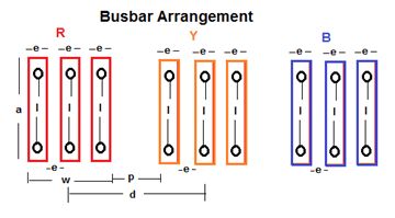
Calculation:
(1) De rating Factors for Bus bar:
- (1) Per Phase Bus Strip De rating Factor (K1):
- Bus bar Width(e) is 75mm and Bus bar Length per Phase(a) is 500mm so e/a is 75/500=0.15
- No of Bus bar per phase is 2 No’s.
- From following table value of de rating factor is 1.83
|
Number of Bus Bar Strip per Phase (K1) |
|||
| e/a | No of Bus Bar per Phase | ||
| 1 | 2 | 3 | |
| 0.05 | 1 | 1.63 | 2.4 |
| 0.06 | 1 | 1.73 | 2.45 |
| 0.08 | 1 | 1.76 | 2.5 |
| 0.1 | 1 | 1.8 | 2.55 |
| 0.12 | 1 | 1.83 | 2.6 |
| 0.14 | 1 | 1.85 | 2.63 |
| 0.16 | 1 | 1.87 | 2.65 |
| 0.18 | 1 | 1.89 | 2.68 |
|
0.2 |
1 | 1.91 | 2.7 |
- (2) Bus bar Insulating Material De rating Factor (K2)
- Bus bar having No insulating material. It is Bare so following Table
- De rating Factor is 1.
| Bus Bar Insulating Material (K2): | De rating Factor |
| Bare | 1 |
| PVC Sleeving | 1.2 |
| Painted | 1.5 |
- (3) Bus bar Position De rating Factor (K3)
- Bus bar Position is Edge-mounted bars so following Table
- De rating Factor is 1
| Bus Bar Position(K3): | De rating Factor |
| Edge-mounted bars | 1 |
| 1 bar base-mounted | 0.95 |
| several base-mounted bars | 0.75 |
- (4) Bus bar Installation Media De rating Factor (K4)
- Bus bar Installation Media is Non-ventilated ducting so following Table
- De rating Factor is 0.8
| Bus Bar Installation Media(K4): | De rating Factor |
| Calm indoor atmosphere | 1 |
| Calm outdoor atmosphere | 1.2 |
| Non-ventilated ducting | 0.8 |
- (5) Bus bar Artificial Ventilation De rating Factor (K5)
- Bus bar Installation Media is Non-ventilated ducting so following Table
- De rating Factor is 0.9
| Bus Bar Artificial Ventilation Scheme (K5): | De rating Factor |
| without artificial ventilation | 0.9 |
| with artificial ventilation | 1 |
- (6) Enclosure & Ventilation De rating Factor (K6)
- Bus bar Area per Phase = Bus width X Bus Thickness X Length of Bus X No of Bus bar per Phase
- Bus bar Area per Phase = 75x10xX500X2= 750000mm
- Total Bus bar Area for Enclosure= No of Circuit X( No of Phase + Neutral )X Bus bar Area per Phase
- Here we used Size of Neutral Bus is equal to Size of Phase Bus
- Total Bus bar Area for Enclosure=3X(3+1)X750000mm
- Total Bus bar Area for Enclosure=9000000 Sq.mm
- Total Enclosure Area= width X Height X Length
- Total Enclosure Area=1200x600x2400=1728000000 Sq.mm
- Total Bus bar Area for Enclosure / Total Enclosure Area =9000000/1728000000
- Total Bus bar Area for Enclosure / Total Enclosure Area=0.53%
- Bus bar Artificial Ventilation Scheme is without artificial ventilation so following Table
- De rating Factor is 0.95
| Volume of Enclosure & Ventilation De rating Factor (K6) | |||
| cross Section area of Bus bar/Total Bus Bar Area | Indoors ( Panel is well Ventilated) | Indoors ( Panel is Poorly Ventilated) | Outdoor |
| 0% | 0.95 | 0.85 | 0.65 |
| 1% | 0.95 | 0.85 | 0.65 |
| 5% | 0.9 | 0.7 | 0.6 |
| 10% | 0.85 | 0.65 | 0.5 |
- (7) Proxy Effect De rating Factor (K7)
- Bus bar Phase Spacing (p) is 400mm.
- Bus bar Width (e) is 75mm and Space between each bus of Phase is 75mm so
- Total Bus length of Phase with spacing (w) =75+75+75+75+75=225mm
- Bus bar Phase Spacing (p) / Total Bus length of Phase with spacing (w) = 400 / 225 =2
- From following Table De rating factor is 0.82
| Proxy Effect (K7): | De rating Factor |
| 1 | 0.82 |
| 2 | 0.82 |
| 3 | 0.82 |
| 4 | 0.89 |
| 5 | 0.95 |
| 6 | 0.99 |
| 7 | 1 |
- (8) Altitude of Bus Bar installation De rating Factor (K8)
- Altitude of Panel Installation on Site is 2000 meter so following Table
- De rating Factor is 0.88
| Altitude of installation site (Meter) (K8) | De rating Factor |
| 2200 | 0.88 |
| 2400 | 0.87 |
| 2500 | 0.86 |
| 2700 | 0.85 |
| 2900 | 0.84 |
| 3000 | 0.83 |
| 3300 | 0.82 |
| 3500 | 0.81 |
| 4000 | 0.78 |
| 4500 | 0.76 |
| 5000 | 0.74 |
- Total De rating Factor= K1XK2XK3Xk4Xk5Xk6Xk7Xk8
- Total De rating Factor =1.83x1x1x0.8×0.9×0.95×0.82×0.88
- Total De rating Factor =0.90
(2) Bus bar Size Calculation:
- Desire Current Rating of Bus bar (I2) =630 Amp
- Current Rating of Bus bar after De rating Factor (I1)= I2 X De rating Factor or I2 / De rating Factor
- Current Rating of Bus bar after De rating Factor (I1)=630×0.9
- Current Rating of Bus bar after De rating Factor (I1)=697Amp
- Bus bar Cross Section Area as per Current= Current Rating of Bus bar / Current Density of Material
- Bus bar Cross Section Area as per Current= 697 / 1.6
- Bus bar Cross Section Area as per Current= 436 Sq.mm
- Bus bar Cross Section Area as per Short Circuit= Isc X√ ((K/( θtx100)x(1+ α20xθ) xt
- Bus bar Cross Section Area as per Short Circuit= 50000X√ ((1.166/( 100×100)x(1+ 0.00403×85) x1
- Bus bar Cross Section Area as per Short Circuit=626 Sq.mm
- Select Higher Size for Bus bar Cross section area between 436 Sq.mm and 626 Sq.mm
- Final Calculated Bus Bar Cross Section Area =626 Sq.mm
- Actual Selected Bus bar size is 75×10=750 Sq.mm
- We have select 2 No’s of Bus bar per Phase hence.
- Actual Bus bar cross section Area per Phase =750×2= 1500 Sq.mm
- Actual Cross Section Area of Bus bar =1500 Sq.mm
- Actual Bus bar Size is Less than calculated Bus bar size.
(3) Forces generated on Bus Bar due to Short Circuit Current
- Peak electro-magnetic forces between phase conductors (F1) = 2X(l/d)X(2.5xIsc)2/100000000
- Total width of Bus bar per Phase(w)=75+75+75=225mm =2.25cm
- Bus bar Phase to Phase Distance (d)=400+225=625mm=6.25cm
- Peak electro-magnetic forces between phase conductors (F1) =2x(50/63)x(2.5×50000)2/100000000
- Peak electro-magnetic forces between phase conductors (F1)=250 Kg /cm2
- Peak electro-magnetic forces between phase conductors (F1)=2.5 Kg /mm2
- Actual Forces at the head of the Supports or Bus Bar (F)=F1X(H+h/H)
- Actual Forces at the head of the Supports or Bus Bar (F)=2.5x(100+5/100)
- Actual Forces at the head of the Supports or Bus Bar (F)= 3 Kg /mm2
- Permissible Strength of Insulator (F’) is 10 Kg/mm2
- Actual Forces at the head of the Supports or Bus Bar is less than Permissible Strength
- Forces on Insulation is in within Limits
(4) Mechanical strength of the bus bars
- Mechanical strength of the bus bars=(F1X i /12)x(1/ Modulus of inertia of a bus bar )
| Value of Modulus of inertia of a bus bar or of a set of bus bars (i/v) | ||
| No of Bus Strip per Phase | Vertical Bus Bar (cm3) | Horizontal Bus Bar (cm3) |
| 1 | 1.66 | 16.66 |
| 2 | 14.45 | 33.33 |
| 3 | 33 | 50 |
- From above table Value of Modulus of inertia of a bus bar=14.45
- Mechanical strength of the bus bars=(250×50/12)X(1/14.45)
- Mechanical strength of the bus bars= 72 Kg/cm2
- Mechanical strength of the bus bars= 0.72 Kg/mm2
- Permissible Bus bar Strength is 12 Kg/mm2
- Actual Mechanical Strength is less than Permissible Strength
- Mechanical strength of Bus bar is in within Limit
(5) Temperature Rise Calculation
- Specified Maximum Temperature Rise (T1) is 35°c
- Calculated Maximum Temperature Rise (T2)=T/(log(I1/I2)1.64)
- Calculated Maximum Temperature Rise (T2)=35/(Log(697/630)1.64)
- Calculated Maximum Temperature Rise (T2)= 30°c
- Calculated Bus bar Temperature rise is less than Specified Max Temperature rise
- Temperature Rise is in within Limit
Results:
- Size of Bus bar = 2No’s 75x10mm per Phase.
- Total No of Feeder =3 No’s
- Total No’s of Bus bar = 6 No’s 75x10mm for Phase and 1No’s 75x10mm for Neutral.
- Forces at the head of the Supports or Bus Bar (F)= 3kg/mm2
- Mechanical strength of the bus bars= 0.7 Kg/mm2
- Maximum Temperature Rise=30°c
 JIGNESH PARMAR





THIS IS GOOD REFERENCE FOR LV AND MV SWGR. DESIGNERS.
Extremely useful information
Thank u for this useful information.Great
Hi, Mr. Jignesh Parmar,
The above information is really useful for us who ever doing the design and selection of busbar for panel engineering.
Thanks for this information, kindly share electrical technical information to us.
Ganapathy.
thank alot for this valuable information however, I notice that you are considering derating factor for busbar calcualtion is 0.9 then after derating current rating shall be reduced but in your calculation it is increasing. can you please explain why it is so or it is only a typing mistake.
CAN I USE HALF GRADE COPPER BUS BAR 15X100 MM FOR 2500AMPS AC 50HZ
Actually the current will be divided by derating factor.
thank u sir, for this information
useful information
Dear sir,
This information very much use to new design Engineer.
Hitesh parikh
Design Engineer in MV SWGR company
Truly useful. Thanks for sharing.
Dear Sir,
thanks for your above article, I also want the same type of calculation for Earthing bus bar(Conductor) for electrical panel.
Thanks Sir,
I need more elaboration on the temperature rise calculation. I am not able to get the answer 30 in the given example. Deg cel with the given formula. My T1= 40 Deg cel, I1= 4055 Amp, I2= 4000 Amp , T2= ?
: Calculated Maximum Temperature Rise (T2)=35/(Log(697/630)1.64)
Pl help,
Thx,
Datta
Good Info,
Thanks for detail and calculation,good for RMU and CSU design.
Thank you for your information.I am doing Air core reactor designs myself.I know the temperature rise of the conductor.It is R&D ..I am not getting Economical Designs…They are going very large size for smaller current and impedance… Will you pleas help to do learn reactor design….I am doing this research my self from last one year..
Dear Sir,
Very use ful information you have given to us. Thank you . I have one doubt . Can you please tell me why we choose 2nos of 75X10 bus bar for each phase when one is enough for the Isc rating. Is there anything else we have to know.
sir,
i want to learn more from u……
Ji,
Let me know the factors reference for PVC sleeve & matt black painted busbar.
hi,
nice info indeed.
i’d also like to know how you chose the above bus bar size and please post the board with the bus bar dimensions.
thanks
thank
you sir
Thanks a lot brother
How these de rating factors are already been calculated? Please explain?
Hello Sir,
Thanks for the information but I have one doubt . Can you please tell me why we choose 2 nos of 75X10 bus bar for each phase when one is enough for the Isc rating. Is there anything else we have to know.
Which standard reference you have considered ?
Thanks,
Vipin
Dear Sir,
Please provide following information given below-
1- How to select Al Bus bar (Info of Al Bus bar Material )
2-How to compare Al and Cu Bus bar to select for same rating.
3-Any thumb rule is there to select bus bar size quickly.
4-Please provide bus bar selection chart for AL and Cu Both.
5-How to select no, of Bus bar per phase.
Thank u sir, this will help me a lot in my field of job…
Very Usefull document….
Power distribution load centers generally have 2 methods of current supply. Source current is either introduced at one end of the bus (top fed) with branch circuit loads distributed through taps and over-current devices along the bus. Many smaller capacity load centers (100-225 amperes) have current supplied through a main breaker connected to the mid-section of a bus. How is bus design affected with a center fed approach as opposed to a top fed approach? Did your calculation assume the top fed design approach? Thank you
Can you refer to relevant IS/IEEE/IEC Standard that you followed for these calculations? You may mail me at: “sreeraasi94@gmail.com”
Dear it will be helpful for me too have this reference, luca_211177@libero.it
Thanks and regards
can provide bus bar size calculation for 3sec
Nice
hello sir i have 63 A mcb 24 nos out going. so what would be a main incommer.
Very thankful to you
Dear Sir,
Please provide following information given below-
1- How to select Al Bus bar (Info of Al Bus bar Material )
2-How to compare Al and Cu Bus bar to select for same rating.
3-Any thumb rule is there to select bus bar size quickly.
4-Please provide bus bar selection chart for AL and Cu Both.
5-How to select no, of Bus bar per phase.
Jignesh .Parmar,
Its a blessing that you are maintaining this site……
Someone explains to me: Number of Bus Bar Strip per Phase (K1)..What is bus bar strip
Please tell me what is the formula for determine MCCB maximum working temperature..?
Thanks a lot for sharing such a useful article
Dear Sir,
Please explain why did u take 50 deg. C as ambient temperature? Is it actual ambient temperature of settled value after temperature has risen due to heat emitted?
Thanks
Thankyou for all your usefull refference. And 1 question Ihave small power plant with 1 set 500 kva cat,365 kva cat, n 100 kva cummin eng I want to built synchronize both of thre genset for safe operation and load sharing….best regard Bambaang Yuwono.
Dear Sir,
I want to design a Bus bar of rating 700V, 130A DC supply , then what is thinkness of bus bar size when it is a copper material
Thankyou for all your usefull refference. And 1 question Ihave small power plant with 1 set 500 kva cat,365 kva cat, n 100 kva cummin eng I want to built synchronize both of thre genset for safe operation and load sharing….best regard Bambaang Yuwono.
how to select busbar as per rating changes of panel… for eg.. 1000A ACB, 2500A ACB … WHICH SIZE OF BUSBAR
WE HAVE SELECT
Please let me know about I/d(50/63) for F1
N.M.badsha
Electrical & Electronic Engineer,KUET
Experience on power Distribution,pharmaceutical,Food & Beverage Production Machineries.
Hi – is there any reference document to substantiate the consideration of current density 1.6A/mm2
thank you sir for sharing your valuable knowledge
Sir,
Pl.provide us design calculation for AMF Panel bus bar size – Both three phases & one neutral ,we have three DG Set which are 500KVA each and controlled by 800A / 1600A ACB with protection
MD GULSHAD KHAN
IT IS A VERY USEFUL CALCULATION FOR SELECTING THE BUSBAR
can you please clarify me, for HIGH RISE Buildings , Bus bars are used instead of only using armored cables . Is this because of economical factor or any technical advantage is there.?
Tanks, it is very useful
If it is possible for you, please tell us about your standard or document reference.
Best regards.
can i use half grade copper bus bar for 1000amps cos formula
Greetings to you Mr.Jignesh Parmar.
You are doing a great service yo practicing engineers.After all, teaching is a noble way of serving the people.
can iuse half grade copper bas bar 500&1000amps change over switch formula?
thanks for this useful information. which standards are applicable to this calculation.
Thanks for bus bar information
Item(6) De-rating Factor K6:
Area of Busbar is mentioned as Width x Thickness x Length.x No.of busbars. How can the product of these three dimensions be “area”, it can be only “volume”; Please clarify.
thanks for the information
you want panel board design for LT switchgear & current rating busbar calculation (copper & Aluminium)
According to which IEC standard is performed this calculation?
any one knows how to find bus bar size with a only amps rating. because i dont know about the bus bar size mean, how could i find the bus bar rating with a only amps. any one know the formulas ?????
it will be gr8 if you provide backup sheet (All table source))for above calculations.
thnks for the information sir,, can you post a quick thumb rule to check the size of busbar with respect to CB used (ex.800A MCCB/ACB etc)
I request you to please mention reference IS / IEC standard for better understanding
As per temperature rise calculation : Source Reference : IEC 62271 – 1
great job sir……………..thanks for the info
the above mentioned explanation is based on which Forum or what?
Current Rating of Bus bar after De rating Factor (I1)= 0.9*630 = 567 or 697 ???
it’s a typographical error…should be
630/.9
KINDLY PROVIDE US WITH THE RELATION BETWEEN BUS BAR SIZING AND INTERNAL SEPARATION
For outdoor installation, factor k6 has to be 0.95,0.9 & 0.85. For Indoor installation with poor ventilation, k6 to be 0.65,0.6 & 0.5.
Thanks Mr. Parmar, I was looking for data related to the torque limits for the bus bar joints and its impact on temperature rise of bus bars during normal usage. Are there any methods to deduce temperature during full load conditions based on temperatures available during part load condition of the system ( like we have seen temperature rise near MCCB 630 A terminals of 55deg above ambient of 35 deg at a constant load of 300A, what would be temp at say 600A, is 55+35 = 90Deg acceptable at 50% load )
Sir,in bus bar size calculation from where we get the values of alpha, Dita,and Dita t
Please advise from which standard the derating factors are taken
can i share this on my personal blog ???
really useful info !!!
dear sir ,
Confirm temperature inside outdoor Metering panel when carrying full load current at an ambient of 40 Deg.C.
It is a very usefull calculation, which could serve my present requirement. In future pls forward the useful eletrical calculation to my mail id. Thank you.
Could you help me to forward the cu bus bar-bar dimensions(wdth x thknss ) for 1000Amp, 500Amp, 300Amp, & 200Amp Bar .
how to calculate Resistivity of copper bus bar
hi jignesh
can you mail me copy of Indal text book and Thomas & rata text book if you have.
regards
pavitraagal@gmail.com
+91-9826719220
Dear Ms. Pavitra, Just now I have sent the book by mail to your above mail ID. Please acknowledge receipt.
This gives the volume of the right, how you considered it as area?
sir kindly show me the calculator of selection switch gear and cable size
Dear Jignesh
This is very useful technical information which you share
Thanks
Sir,
How to calculate bus duct earthing size
Hi Jignesh,
I need to know the temperature of a copper busbar and steel pad at 12.5KA ISC fault level for 2 sec. if we know the size of bus bar or spade?
Rajesh
Dear Jignesh,
Will You please give me t Busbar calculation for 1250 Amps, Alluminium, PMCC Panel, Permissible Temp 45 Deg C, InsulatedHeat Shrink Sleeves, Volatge 415 V , 50 Hz, Humid Atmosphere Assam-Noonmati.. Regards, Kamal Trivedi (kamaltrivedi@ymail.com
Dear Sir,
On which standard basis, your made panel sizing and calculation. which is not specified. Kindly clarify.
Thanks & Regards,
K. Ranjith
Dear sir
Could u please share the derivation for that formula to calculate area of busbar as per the short circuit capacity please.
What will be the magnitude of current of one 1600 KVA 3 phase Transformer at its LV winding side.
The manufacturer has consider the Busbar size is 100×12 mm=1200 sq.mm.copper Bus single. what is the Current density of the Copper and is the Busbar size sufficient for that Transformer?
Hi
Could you please explain about Various Testing in ACB & Protection Relay.
Kindly confirm the name of the standard followed by you to arrive at the formulae defined above and how shall be the approach to calculate for DC currents.
Yes no where any standard and reference has been mentioned.
Can this calculation applies for Busbar design in relays and contactors
Can you please let me know below mentioned parameter in case of Aluminium bus bar
1) Temperature Co efficient of Material Resistance at 20°c(α20)=
2) Material Constant(K)=
3) Bus bar Material Permissible Strength=
Sir i want BUS Bar Capacity and Size for250 Amps incomer MCCB and 100 Amps MCCB-07 Nos out going
how to choose material constant value?
As per which IS/IEC standard is this calculation performed??
Hi Sir,
Any standard of MDB & SMDB incoming and out goings standard Fault rating (kA) . ex SMDB incoming 35kA , SMDB Out goings for DB-25kA , MCC – 35kA.
Please clarify
Thanks,
Munavar
All calculation above mentioned are nice i got result same as you, but in “TEMPERATURE RISE CALCULATION” how would you get 30 deg.C as maximum temperature rise.
please explain.
Dear Sir,
Please help me for find 1250A copper bus bar size as per temperature rise with Calculation and formula
Hello dear
in electrical panels, the main bus bar and sub bus bar size is different ? or the same ?
I want to know the size of bus bar
hello, what if I need to compute for the total ampacity for more than 3 busbars per phase? what data do I follow for K1?
Dear Jignesh,
Can you please let me know source reference for insulation material on busbars PVC Sleeve / Painted???
Sir, what is the material constant for aluminium busbar K=?
Hello sir,
MULTIPLICATION ERROR.
Current Rating of Bus bar after De rating Factor (I1)=630×0.9
Current Rating of Bus bar after De rating Factor (I1)=697Amp
Hello Sir,
I have some doubts in your bus bar sizing calculation sheet
1. Is operating and Final Temperature of Bus bar during Fault are same for Aluminium and Copper
2. I am not getting how is Bus bar Position: i.e. Edge mounted, 1 bar base mounted, several base mounted
3. What is the Bus bar Material Permissible Strength: for aluminium.
Please reply to queries
Based on the busbar sizing calculation, understood that 1 run of 75X10 mm for phase busbar is sufficient . whereas in actual bus bar size 2 runs of 75 X 10 mm. is it required to go with 2 runs of busbar. ??? Is this is oversizing of busbar ..? Please explain
Sir , long distance low voltage cable selecting sizes example 650 amp load and distance 500 mtr and voltage 400 so what’s size of cable will be use …
What is the technical reference or Indian standard reference for this design?
Thus u have calculated for aluminium or copper.
sir in 11kv system 3200a what size aluminium bu bar to consider
what would be the cross sectional area of busbar for 250A on 50KA 1sec
VERY GOOD INFORMATION CAN YOU CALULATE FOR 1250A BUSBAR copper.
Sir, can I have reference about the Derating factor K2 (insulating media) I. E. what is the source of it.
Thanks sir,
For good inormation
Please confirm the Copper busbar for 4000A Breaker -2 no 75KA Rating Panel width 3.5 Meter Height -2.3m
please,
explain me , 3 phase ,400volt, 7000amp rating copper bus bar. please give me calculation busbar to busbar how much gap.
i want to how much gap busbar to busbar.
spacing between bus …..elaborate .?
In K2 below, why when use PVC sleeving & painted, the current capacity rating of busbar is increase ?
2) Bus bar Insulating Material De rating Factor (K2)
Bus bar having No insulating material. It is Bare so following Table
De rating Factor is 1.
Bus Bar Insulating Material (K2): De rating Factor
Bare 1
PVC Sleeving 1.2
Painted 1.5
what is the distance (in mm ) between the busbar in secondery selective arrangment
Hello Sir,
Can you help me for the calculation of Busbar size in sandwich busduct design
Hi,
Please define well ventilated and poorly ventilated Indoor room
VINOD KUMAR says:
September 25, 2019 at 10:37 am
All calculation above mentioned are nice i got result same as you, but in “TEMPERATURE RISE CALCULATION” how would you get 30 deg.C as maximum temperature rise.
please explain…….. Mr. Parmar, is this question kept open without answering since 2019?
I am also not getting 30degrees centigrade….There must be something wrong in the formula or value indicated ….Pl explain
please provide the Aluminum constant (k) value ?
what is the material of constant pls explain?
what will be the output busbar ampere ratings in panel for 1250A ACB incommer.