Current Transformer
April 16, 2011 151 Comments
Current transformers
Principle of operation of CT
- A current transformer is defined as “as an instrument transformer in which the secondary current is substantially proportional to the primary current (under normal conditions of operation) and differs in phase from it by an angle which is approximately zero for an appropriate direction of the connections.”
- Current transformers are usually either “measuring” or “protective” types.
Some Definitions used for CT:
1) Rated primary current:
- The value of primary current which appears in the designation of the transformer and on which the performance of the current transformer is based.
2) Rated secondary current:
- The value of secondary current which appears in the designation of the transformer and on which the performance of the current transformer is based.
- Typical values of secondary current are 1 A or 5 A. In the case of transformer differential protection, secondary currents of 1/ root 3 A and 5/ root 3 A are also specified.
3) Rated burden:
- The apparent power of the secondary circuit in Volt-amperes expressed at the rated secondary current and at a specific power factor (0.8 for almost all standards)
4) Rated output:
- The value of the apparent power (in volt-amperes at a specified power (factor) which the current transformer is intended to supply to the secondary circuit at the rated secondary current and with rated burden connected to it.
5) Accuracy class:
- In the case of metering CT s, accuracy class is typically, 0.2, 0.5, 1 or 3.
- This means that the errors have to be within the limits specified in the standards for that particular accuracy class.
- The metering CT has to be accurate from 5% to 120% of the rated primary current, at 25% and 100% of the rated burden at the specified power factor.
- In the case of protection CT s, the CT s should pass both the ratio and phase errors at the specified accuracy class, usually 5P or 10P, as well as composite error at the accuracy limit factor of the CT.
6) Current Ratio Error:
- The error with a transformer introduces into the measurement of a current and which arises from the fact that actual transformation ratio is not equal to the rated transformer ratio. The current error expressed in percentage is given by the formula:
- Current error in % = (Ka(Is-Ip)) x 100 / Ip
- Where Ka= rated transformation ratio ,Ip= actual primary current, Is= actual secondary current when Ip is flowing under the conditions of measurement
7) Accuracy limit factor:
- The value of primary current up to which the CT complies with composite error requirements. This is typically 5, 10 or 15, which means that the composite error of the CT has to be within specified limits at 5, 10 or 15 times the rated primary current.
8) Short time rating:
- The value of primary current (in kA) that the CT should be able to withstand both thermally and dynamically without damage to the windings, with the secondary circuit being short-circuited. The time specified is usually 1 or 3 seconds.
9) Instrument security factor (factor of security):
- This typically takes a value of less than 5 or less than 10 though it could be much higher if the ratio is very low. If the factor of security of the CT is 5, it means that the composite error of the metering CT at 5 times the rated primary current is equal to or greater than 10%. This means that heavy currents on the primary are not passed on to the secondary circuit and instruments are therefore protected. In the case of double ratio CT’s, FS is applicable for the lowest ratio only.
10) Class PS X CT:
- In balance systems of protection, CT s with a high degree of similarity in their characteristics is required. These requirements are met by Class PS (X) CT s. Their performance is defined in terms of a knee-point voltage (KPV), the magnetizing current (Imag) at the knee point voltage or 1/2 or 1/4 the knee-point voltage, and the resistance of the CT secondary winding corrected to 75C. Accuracy is defined in terms of the turn’s ratio.
11) Knee point voltage:
- That point on the magnetizing curve where an increase of 10% in the flux density (voltage) causes an increase of 50% in the magnetizing force (current).
- The ‘Knee Point Voltage’ (Vkp) is defined as the secondary voltage at which an increase of 10% produces an increase in magnetizing current of 50%. It is the secondary voltage above which the CT is near magnetic saturation.
12) Core balance CT (CBCT):
- The CBCT, also known as a zero sequence CT, is used for earth leakage and earth fault protection. The concept is similar to the RVT. In the CBCT, the three core cable or three single cores of a three phase system pass through the inner diameter of the CT. When the system is fault free, no current flows in the secondary of the CBCT. When there is an earth fault, the residual current (zero phase sequence current) of the system flows through the secondary of the CBCT and this operates the relay. In order to design the CBCT, the inner diameter of the CT, the relay type, the relay setting and the primary operating current need to be furnished.
13) Phase displacement:
- The difference in phase between the primary and secondary current vectors, the direction of the vectors being so chosen that the angle is zero for the perfect transformer. The phase displacement is said to be positive when the secondary current vector leads the primary current vector. It is usually express in minutes
14) Highest system voltage:
- The highest rms line to line voltage which can be sustained under normal operating conditions at any time and at any point on the system. It excludes temporary voltage variations due to fault condition and the sudden disconnection of large loads.
15) Rated insulation level:
- That combination of voltage values (power frequency and lightning impulse, or where applicable, lightning and switching impulse) which characterizes the insulation of a transformer with regard to its capability to withstand by dielectric stresses. For low voltage transformer the test voltage 4kV, at power-frequency, applied during 1 minute.
16) Rated short-time thermal current (Ith):
- The rms value of the primary current which the current transformer will withstand for a rated time, with their secondary winding short circuited without suffering harmful effects.
17) Rated dynamic current (Idyn):
- The peak value of the primary current which a current transformer will withstand, without being damaged electrically for mechanically by the resulting electromagnetic forces, the secondary winding being short-circuited.
18) Rated continuous thermal current (Un)
- The value of current which can be permitted to flow continuously in the primary winding, the secondary windings being connected to the rated burdens, without the temperature rise exceeding the specified values.
19) Instrument security factor (ISF or Fs):
- The ratio of rated instrument limits primary current to the rated primary current. The times that the primary current must be higher than the rated value, for the composite error of a measuring current transformer to be equal to or greater than 10%, the secondary burden being equal to the rated burden. The lower this number is, the more protected the connected instrument are against.
20) Sensitivity
- Sensitivity is defined as the lowest value of primary fault current, within the protected zone, which will cause the relay to operate. To provide fast operation on an in zone fault, the current transformer should have a ‘Knee Point Voltage’ at least twice the setting voltage of the relay.
21) Field Adjustment of Current Transformer Ratio:
- The ratio of current transformers can be field adjusted to fulfil the needs of the application. Passing
more secondary turns or more primary turns through the window will increase or decrease the turns ratio.
Actual Turns Ratio = (Name Plate Ration- Secondary Turns Added) / Primary Turns.
Types of Current transformers (CT’s)
According to Construction of CT:
1) Bar Type:
- Bar types are available with higher insulation levels and are usually bolted to the current caring device.
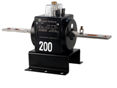
- Bar type current transformers are insulated for the operating voltage of the system.
- Bar-type CTs operate on the same principle of window CTs but have a permanent bar installed as a primary conductor
2) Wound CT’s:
- Capacity: There are designed to measure currents from 1 amp to 100 amps.
- the most common one is the wound type current transformer. The wound type provides excellent performance under a wide operating range. Typically, the wound type is insulated to only 600 volts.
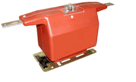
- Since the load current passes through primary windings in the CT, screw terminals are provided for the load and secondary conductors. Wound primary CT’s are available in ratios from 2.5:5 to 100:5.
- Wound CTs have a primary and secondary winding like a normal transformer. These CTs are rare and are usually used at very low ratios and currents, typically in CT secondary circuits to compensate for low currents, to match different CT ratios in summing applications, or to isolate different CT circuits. Wound CTs have very high burdens, and special attention to the source CT burden should be applied when wound CTs are used.
3) Window:
- Window CTs are the most common. They are constructed with no primary winding and are installed around the primary conductor. The electric field created by current flowing through the conductor interacts with the CT core to transform the current to the appropriate secondary output. Window CTs can be of solid or split core construction. The primary conductor must be disconnected when installing solid window CTs. However, split core CTs can be installed around the primary conductor without disconnecting the primary conductor
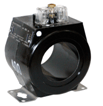
- Ring Core CT’s :
- Capacity: There are available for measuring currents from 50 to 5000 amps
- Size: with windows (power conductor opening size) from 1″ to 8″ diameter.
- Split Core CT’s:
- Capacity: There are available for measuring currents from 100 to 5000 amps.
- Size: with windows in varying sizes from 1″ by 2″ to 13″ by 30″.
- Split core CT’s have one end removable so that the load conductor or bus bar does not have to be disconnected to install the CT.
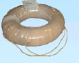
4) Bushing
- Bushing CTs are window CTs specially constructed to fit around a bushing. Usually they cannot be accessed, and their nameplates are found on the transformer or circuit-breaker control cabinets.
- The bushing type is typically used around the bushing on circuit breakers and transformers and may not have a hard protective outside cover.
- Donut type current transformers are typically insulated for 600 volts. To ensure accuracy, the conductor should be positioned in the center of the current transformer opening.
According to Application of CT:
1) Measuring CT:
- The principal requirements of a measuring CT are that, for primary currents up to 120% or 125% of the rated current, its secondary current is proportional to its primary current to a degree of accuracy as defined by its “Class” and, in the case of the more accurate types, that a specified maximum phase angle displacement is not exceeded.
- A desirable characteristic of a measuring CT is that it should “saturate” when the primary current exceeds the percentage of rated current specified as the upper limit to which the accuracy provisions apply. This means that at these higher levels of primary current the secondary current is less than proportionate. The effect of this is to reduce the extent to which any measuring device connected to the CT secondary is subjected to current Overload.
- On the other hand the reverse is required of the protective type CT, the principal purpose of which is to provide a secondary current proportional to the primary current when it is several, or many, times the rated primary current. The measure of this characteristic is known as the “Accuracy Limit Factor” (A.L.F.).
- A protection type CT with an A.L.F. of 10 will produce a proportional current in the secondary winding (subject to the allowable current error) with primary currents up to a maximum of 10 times the rated current.
- It should be remembered when using a CT that where there are two or more devices to be operated by the secondary winding, they must be connected in series across the winding. This is exactly the opposite of the method used to connect two or more loads to be supplied by a voltage or power transformer where the devices are paralleled across the secondary winding.
- With a CT, an increase in the burden will result in an increase in the CT secondary output voltage. This is automatic and necessary to maintain the current to the correct magnitude. Conversely, a reduction in the burden will result in a reduction in the CT secondary output voltage.
- This rise in secondary voltage output with an increase in burden means that, theoretically, with infinite burden as is the case with the secondary load open circuit, an infinitely high voltage appears across the secondary terminals. For practical reasons this voltage is not infinitely high, but can be high enough to cause a breakdown in the insulation between primary and secondary windings or between either or both windings and the core. For this reason, primary current should never be allowed to flow with no load or with a high resistance load connected across the secondary winding.
- When considering the application of a CT it should be remembered that the total burden imposed on the secondary winding is not only the sum of the burden(s) of the individual device(s) connected to the winding but that it also includes the burden imposed by the connecting cable and the resistance of the connections.
- If, for example, the resistance of the connecting cable and the connections is 0.1 ohm and the secondary rating of the CT is 5A, the burden of the cable and connections (RI2) is 0.1 x 5 x 5 = 2.5VA. This must be added to the burden(s) of the connected device(s) when determining whether the CT has an adequately large burden rating to supply the required device(s) and the burden imposed by the connections.
- Should the burden imposed on the CT secondary winding by the connected device(s) and the connections exceed the rated burden of the CT the CT may partly or fully saturate and therefore not have a secondary current adequately linear with the primary current.
- The burden imposed by a given resistance in ohms [such as the resistance of a connecting cable] is proportional to the square of the rated secondary current. Therefore, where long runs of cable between CT and the connected device(s) are involved, the use of a 1A secondary CT and a 1A device rather than 5A will result in a 25-fold reduction in the burden of the connecting cables and connections. All burden ratings and calculations are at rated secondary current.
- Because of the foregoing, when a relatively long [more than a very few meters] cable run is required to connect a CT to its burden [such as a remote ammeter] a calculation should be made to determine the cable burden. This is proportional to the “round trip” resistance, i.e. twice the resistance of the length of twin cable used. Cable tables provide information on the resistance values of different sizes of conductors at 20o C per unit length.
2) Protective CT:
- The calculated resistance is then multiplied by the square of the CT secondary current rating [25 for 5A, 1 for 1A]. If the VA burden as calculated by this method and added to the rated burden(s) of the device(s) to be driven by the CT exceeds the CT burden rating, the cable size must be increased [to reduce the resistance and thus the burden] or a CT with a higher VA burden rating must be used, or a lower CT secondary current rating [with matching change in the current rating of the device(s) to be driven] should be substituted
Nomenclature of CT:
- Ratio: input / output current ratio
- Burden (VA): total burden including pilot wires. (2.5, 5, 10, 15 and 30VA.)
- Class: Accuracy required for operation (Metering: 0.2, 0.5, 1 or 3, Protection: 5, 10, 15, 20, 30).
- Accuracy Limit Factor:
- Dimensions: maximum & minimum limits
- Nomenclature of CT: Ratio, VA Burden, Accuracy Class, Accuracy Limit Factor.
- Example: 1600/5, 15VA 5P10 (Ratio: 1600/5, Burden: 15VA, Accuracy Class: 5P, ALF: 10)
- As per IEEE Metering CT: 0.3B0.1 rated Metering CT is accurate to 0.3 percent if the connected secondary burden if impedance does not exceed 0.1 ohms.
- As per IEEE Relaying (Protection) CT: 2.5C100 Relaying CT is accurate within 2.5 percent if the secondary burden is less than 1.0 ohm (100 volts/100A).
1) Current Ratio of CT:
- The primary and secondary currents are expressed as a ratio such as 100/5. With a 100/5 ratio CT, 100A flowing in the primary winding will result in 5A flowing in the secondary winding, provided the correct rated burden is connected to the secondary winding. Similarly, for lesser primary currents, the secondary currents are proportionately lower.
- It should be noted that a 100/5 CT would not fulfil the function of a 20/1 or a 10/0.5 CT as the ratio expresses the current rating of the CT, not merely the ratio of the primary to the secondary currents.
- The rated secondary current is commonly 5A or 1A, though lower currents such as 0.5A are not uncommon. It flows in the rated secondary load, usually called the burden, when the rated primary current flows in the primary winding.
- Increasing or Decreasing Turns Ratio of CT:
- Increasing Number of Turn: Increasing the number of primary turns can only decrease the turn’s ratio. A current transformer with a 50 to 5 turn’s ratio can be changed to a 25 to 5 turn’s ratio by passing the primary twice through the window.
- Increasing or Decreasing Turns Ratio:
- The turn’s ratio can be either increased or decreased by wrapping wire from the secondary through the window of the current transformer.
- Increasing the turn’s ratio with the secondary wire, turns on the secondary are essentially increased. A 50 to 5 current transformer will have a 55 to 5 ratio when adding a single secondary turn.
- Decreasing the turn’s ratio with the secondary wire, turns on the secondary are essentially decreased. A 50 to 5 current transformer will have a 45 to 5 ratio when adding a single secondary turn.
- Decreasing the turn’s ratio with the primary, accuracy and VA burden ratings are the same as the original configuration.
- Increasing the turn’s ratio with the secondary will improve the accuracy and burden rating.
- Decreasing the turn’s ratio with the secondary will worsen the accuracy and burden rating.
- When using the secondary of a current transformer to change the turn’s ratio, the right hand rule of magnetic fields comes into play. Wrapping the white lead or the X1 lead from the H1 side of the transformer through the window to the H2 side will decrease the turn’s ratio. Wrapping this wire from the H2 side to the H1 side will increase the turn’s ratio.
- Using the black or X2 lead as the adjustment method will do the opposite of the X1(white) lead. Wrapping from the H1 to the H2 side will increase the turns ratio, and wrapping from the H2 to the H1 side will decrease the turns ratio.
2) Burden of CT:
- Common burden ratings of CT: 2.5, 5, 10, 15 and 30VA.
- The external load applied to the secondary of a current transformer is called the “burden”.
- The burden of CT is the maximum load (in VA) that can be applied to the CT secondary.
- The burden can be expressed in two ways.
- The burden can be expressed as the total impedance in ohms of the circuit or the total volt-amperes (VA) and power factor at a specified value of current or voltage and frequency.
- Formerly, the practice was to express the burden in terms of volt-amperes (VA) and power factor, the volt-amperes being what would be consumed in the burden impedance at rated secondary current (in other words, rated secondary current squared times the burden impedance). Thus, a burden of 0.5Ωimpedance may be expressed also as “12.5 VA at 5 amperes,” if we assume the usual 5-ampere secondary rating. The VA terminology is no longer standard, but it needs defining because it will be found in the literature and in old data.
Burden for Measuring CT:
- Total burden of Measuring CT = Sum of Meters Burden in VA (Ammeter, Wattmeter, Transducer etc.) connected in series to the CT secondary circuit + Connecting Secondary Circuit Cable Burden in VA.
- Cable burden = I2 x R x2 L, where I = CT secondary current, R = cable resistance per length, 2L is the tro &fro distance of cable length L from CT to metering circuits. If the proper size and short length of wire is used, cable burden can be ignored.
- The CT secondary circuit load shall not be more than the CT VA rating. If the load is less than the CT burden, all meters connected to the measuring CT should provide correct reading.
- In the case of Measuring Current transformer, the burden depends on the connected meters and quantity of meters on the secondary i.e. no of Ammeters, KWh meters, Kvar meters, Kwh meters, transducers and also the connection cable burden (I2 x R x2 L) to metering shall be taken into account.
- Note Meters burden can be obtained from manufacturer catalogue.
- Selected CT burden shall be more than the calculated burden
Burden for Protecting CT:
- In the case of Protection CTs the burden is calculated in the same way as above except the burden of individual protective relays burden shall be considered instead of meters. The connecting cable burden is calculated in the same way as metering CT
- Total burden of Protection CT=Connecting cable Burden in VA + sum of Protective relays Burden in VA.
- All manufacturers can supply the burden of their individual devices. Although not used very often these days, induction disk over-current devices always gave the burden for the minimum tap setting. To determine the impedance of the actual tap setting being used, First Square the ratio of minimum divide by the actual tap setting used and, second multiply this value by the minimum impedance.
- Suppose an impedance of 1.47 + 5.34j at the 1A tap. To apply the relay at the 4A tap the engineer would multiply the impedance at the 1A taps setting by (1/4)2. The impedance at the 4A tap would be 0.0919 + 0.3338j or 0.3462 Z at 96.4 power factor.
- The CT burden impedance decreases as the secondary current increases, because of saturation in the magnetic circuits of relays and other devices. Hence, a given burden may apply only for a particular value of secondary current. The old terminology of volt-amperes at 5 amperes is most confusing in this respect since it is not necessarily the actual volt amperes with 5 amperes flowing, but is what the volt-amperes would be at 5 amperes
- If there were no saturation. Manufacturer’s publications give impedance data for several values of over current for some relays for which such data are sometimes required. Otherwise, data are provided only for one value of CT secondary current.
- If a publication does not clearly state for what value of current the burden applies, this information should be requested. Lacking such saturation data, one can obtain it easily by test. At high saturation, the impedance approaches the DC resistance. Neglecting the reduction in impedance with saturation makes it appear that a CT will have more inaccuracy than it actually will have. Of course, if such apparently greater inaccuracy can be tolerated, further refinements in calculation are unnecessary. However, in some applications neglecting the effect of saturation will provide overly optimistic results; consequently, it is safer always to take this effect into account.
- It is usually sufficiently accurate to add series burden impedances arithmetically. The results will be slightly pessimistic, indicating slightly greater than actual CT ratio inaccuracy. But, if a given application is so borderline that vector addition of impedances is necessary to prove that the CTÕs will be suitable, such an application should be avoided.
- If the impedance at pickup of a tapped over current-relay coil is known for a given pickup tap, it can be estimated for pickup current for any other tap. The reactance of a tapped coil varies as the square of the coil turns, and the resistance varies approximately as the turns. At pickup, there is negligible saturation, and the resistance is small compared with the reactance. Therefore, it is usually sufficiently accurate to assume that the impedance varies as the square of the turns. The number of coil turns is inversely proportional to the pickup current, and therefore the impedance varies inversely approximately as the square of the pickup current.
- Whether CT is connected in wye or in delta, the burden impedances are always connected in wye. With wye-connected CT the neutrals of the CT and of the burdens are connected together, either directly or through a relay coil, except when a so-called zero phase-sequence-current shunt is used.
- It is seldom correct simply to add the impedances of series burdens to get the total, whenever two or more CT are connected in such a way that their currents may add or subtract in some common portion of the secondary circuit. Instead, one must calculate the sum of the voltage drops and rises in the external circuit from one CT secondary terminal to the other for assumed values of secondary currents flowing in the various branches of the external circuit. The effective CT burden impedance for each combination of assumed currents is the calculated CT terminal voltage divided by the assumed CT secondary current. This effective impedance is the one to use, and it may be larger or smaller than the actual impedance which would apply if no other CTÕs were supplying current to the circuit.
- If the primary of an auxiliary CT is to be connected into the secondary of a CT whose accuracy is being studied, one must know the impedance of the auxiliary CT viewed from its primary with its secondary short-circuited. To this value of impedance must be added the impedance of the auxiliary CT burden as viewed from the primary side of the auxiliary CT; to obtain this impedance, multiply the actual burden impedance by the square of the ratio of primary to secondary turns of the auxiliary CT. It will become evident that, with an auxiliary CT that steps up the magnitude of its current from primary to secondary, very high burden impedances, when viewed from the primary, may result.
- Burden is depending on pilot lead length
- For Metering Class CTs burden is expressed as ohms impedance. For Protection-class CTs burden is express as volt-amperes (VA).
| VA | Applications |
| 1 To 2 VA | Moving iron ammeter |
| 1 To 2.5VA | Moving coil rectifier ammeter |
| 2.5 To 5VA | Electrodynamics instrument |
| 3 To 5VA | Maximum demand ammeter |
| 1 To 2.5VA | Recording ammeter or transducer |
- Burden (VA) of copper wires between instrument & current transformer for 1A and 5A secondary’s
| Cross Section (mm2) |
CT 1 Amp Secondary Burden in VA (Twin Wire) |
|||||
|
Distance |
||||||
| 10 meter | 20 meter | 40 meter | 60 meter | 80 meter | 100 meter | |
|
1.0 |
0.35 |
0.71 |
1.43 |
2.14 |
2.85 |
3.57 |
|
1.5 |
0.23 |
0.46 |
0.92 |
1.39 |
1.85 |
2.31 |
|
2.5 |
0.14 |
0.29 |
0.57 |
0.86 |
1.14 |
1.43 |
|
4.0 |
0.09 |
0.18 |
0.36 |
0.54 |
0.71 |
0.89 |
|
6.0 |
0.06 |
0.12 |
0.24 |
0.36 |
0.48 |
0.6 |
| Cross Section (mm2) |
CT 5 Amp Secondary Burden in VA (Twin Wire) |
|||||
|
Distance |
||||||
| 1 meter | 2 meter | 4 meter | 6 meter | 8 meter | 10 meter | |
|
1.5 |
0.58 |
1.15 |
2.31 |
3.46 |
4.62 |
5.77 |
|
2.5 |
0.36 |
0.71 |
1.43 |
2.14 |
2.86 |
3.57 |
|
4.0 |
0.22 |
0.45 |
0.89 |
1.34 |
1.79 |
2.24 |
|
6.0 |
0.15 |
0.30 |
0.60 |
0.89 |
1.19 |
1.49 |
|
10.0 |
0.09 |
0.18 |
0.36 |
0.54 |
0.71 |
0.89 |
CT Burden Calculation:
- The Actual burden is formed by the resistance of the pilot conductors and the protection relay(s). The resistance of a conductor (with a constant cross-sectional area) can be calculated from the equation:
- R =ƿxL / A
- where ƿ = resistivity of the conductor material (given typically at +20°C) ,L= length of the conductor , A = cross sectional area
- If the resistivity is given in μΩm, the length in meters and the area in mm2, the equation 1 will give the resistance directly in ohms.
- Resistivity: Copper 0.0178 µΩm at 20 °C and 0.0216 µΩm at 75 °C
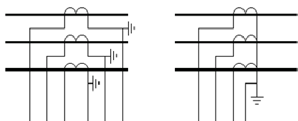
Burden of CT for 4 or 6 wire connection:
- If 6-wire connection is used, the total length of the wire, naturally, will be two times the distance between the CT and the relay. However, in many cases a common return conductor is used as shown in figure then, instead of multiplying the distance by two, a factor of 1.2 is typically used. This rule only applies to the 3-phase connection only. The factor 1.2 allows for a situation, where up to 20% of the electrical conductor length, including terminal resistances, uses 6-wire connection and at least 80% 4-wire connection.

- Example: the distance between the CT and the relay is 5 meters the total length is 2 x 5 m = 10 meter for 6-wire connection, but only 1.2 x 5 m = 6.0 meter when 4-wire connection is used.
Burden of the relay:
- Example: The Distance between the CTs and the protection relay is 15 meters, 4 mm2 Cu conductors in 4-wire connection are used. The burden of the relay input is less than 20 mΩ (5 A inputs). Calculate the actual burden of the CT at 75°C , the input impedance is less than 0.020 Ω for a 5 A input (i.e. burden less than 0.5 VA) and less than 0.100 Ω for a 1 A input (i.e. less than 0.1 VA):
- Solution:
- ƿ = 0.0216 µΩm (75°C) for copper conductor.
- R =ƿxL / A ,R = 0.0216 µΩm x (1.2 x 15 m) / 4 mm2 = 0.097 Ω
- Burden of CT = 0.097 Ω + 0.020 Ω = 0.117 Ω.
- Using CTs of burden values higher than required, is unscientific since it leads to inaccurate reading (meter) or inaccurate sensing of fault / reporting conditions.
- Basically, such high value of design burden extends saturation characteristics of CT core leading to likely damage to the meter connected across it under overload condition. e.g. When we expect security factor (ISF) to be 5, the secondary current should be restricted to less than 5 times in case primary current shoots to more than 5 times its rated value.
- In such an overload condition, the core of CT is desired to go into saturation, restricting the secondary current thus the meter is not damaged. However, when we ask for higher VA, core doesn’t go into saturation due to less load (ISF is much higher than desired) which may damage the meter.
- To understand the effect on Accuracy aspect, let’s take an example of a CT with specified burden of 15 VA, and the actual burden is 2.5 VA:15 VA CT with less than 5 ISF will have saturation voltage of 15 Volts (15/5×5), and actual burden of 2.5 VA the saturation voltage required shall be ( 2.5/5 x 5) 2.5 Volts against 15 Volts resulting ISF = 30 against required of 5.
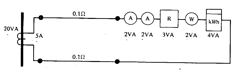
- Example: Decide Whether 5A,20VA CT is sufficient for following circuit
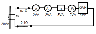
- Total instrument burden = 2 + 2 + 3 + 2 + 4 = 13V A.
- Total pilot load resistance = 2 x 0.1 = 0.2 ohm.
- With 5A secondary current, volt-drop in leads is 5 x 0.2 = 1 V.
- Burden imposed by both leads = 5A x 1 V = 5V A.
- Total burden on CT = 13 + 5 = 18V A.
- As the CT is rated 20V A, it has sufficient margin.
3) Accuracy Class of CT:
- The CT accuracy is determined by its certified accuracy class which is stamped on nameplate. For example, CT accuracy class of 0.3 means that the CT is certified by the manufacturer to be accurate to within 0.3 percent of its rated ratio value for a primary current of 100 percent of rated ratio.
- CT with a rated ratio of 200/ 5 with accuracy class of 0.3 would operate within 0.45 percent of its rated ratio value for a primary current of 100 amps. To be more explicit, for a primary current of 100A it is certified to produce a secondary current between 2.489 amps and 2.511 amps.
- Accuracy is specified as a percentage of the range, and is given for the maximum burden as expressed in VA. The total burden includes the input resistance of the meter and the loop resistance of the wire and connections between the current transformer and meter.
- Example: Burden = 2.0 VA. Maximum Voltage drop = 2.0 VA / 5 Amps = 0.400 Volts.
- Maximum Resistance = Voltage / Current = 04.00 Volts / 5 Amps =0.080 Ohms.
- If the input resistance of the meter is 0.010Ω, then 0.070Ω is allowed for loop resistance of the wire, and connections between the current transformer and the meter. The length and gauge of the wire must be considered in order to avoid exceeding the maximum burden.
- If resistance in the 5 amp loop causes the burden to be exceeded, the current will drop. This will result in the meter reading low at higher current levels.
- As in all transformers, errors arise due to a proportion of the primary input current being used to magnetize the core and not transferred to the secondary winding. The proportion of the primary current used for this purpose determines the amount of error.
- The essence of good design of measuring current transformers is to ensure that the magnetizing current is low enough to ensure that the error specified for the accuracy class is not exceeded.
- This is achieved by selecting suitable core materials and the appropriate cross-sectional area of core. Frequently in measuring currents of 50A and upwards, it is convenient and technically sound for the primary winding of a CT to have one turn only.
- In these most common cases the CT is supplied with a secondary winding only, the primary being the cable or bus bar of the main conductor which is passed through the CT aperture in the case of ring CTs (i .e. single primary turn) it should be noted that the lower the rated primary current the more difficult it is (and the more expensive it is) to achieve a given accuracy.
- Considering a core of certain fixed dimensions and magnetic materials with a secondary winding of say 200 turns (current ratio 200/1 turns ratio 1/200) and say it takes 2 amperes of the 200A primary current to magnetize the core, the error is therefore only 1% approximately. However considering a 50/1 CT with 50 secondary turns on the same core it still takes 2 amperes to magnetize to core. The error is then 4% approximately. To obtain a 1% accuracy on the 50/1 ring CT a much larger core and/or expensive core material is required
- Accuracy Class of Metering CT:
|
Metering Class CT |
|
| Class | Applications |
| 0.1 To 0.2 | Precision measurements |
| 0.5 | High grade kilowatt hour meters for commercial grade kilowatt hour meters |
| 3 | General industrial measurements |
| 3 OR 5 | Approximate measurements |
| Protective System | CT Secondary | VA | Class |
| Per current for phase & earth fault | 1A | 2.5 | 10P20 Or 5P20 |
| 5A | 7.5 | 10P20 Or 5P20 | |
| Unrestricted earth fault | 1A | 2.5 | 10P20 Or 5P20 |
| 5A | 7.5 | 10P20 Or 5P20 | |
| Sensitive earth fault | 1A or 5A | Class PX use relay manufacturers formula | |
| Distance protection | 1A or 5A | Class PX use relay manufacturers formula | |
| Differential protection | 1A or 5A | Class PX use relay manufacturers formula | |
| High impedance differential impedance | 1A or 5A | Class PX use relay manufacturers formula | |
| High speed feeder protection | 1A or 5A | Class PX use relay manufacturers formula | |
| Motor protection | 1A or 5A | 5 | 5P10 |
- Accuracy Class of Letter of CT:
|
Metering Class CT |
|
| Accuracy Class | Applications |
|
B |
Metering Purpose |
|
Protection Class CT |
|
|
C |
CT has low leakage flux. |
|
T |
CT can have significant leakage flux. |
|
H |
CT accuracy is applicable within the entire range of secondary currents from 5 to 20 times the nominal CT rating. (Typically wound CTs.) |
|
L |
CT accuracy applies at the maximum rated secondary burden at 20 time rated only. The ratio accuracy can be up to four times greater than the listed value, depending on connected burden and fault current. (Typically window, busing, or bar-type CTs.) |
- Accuracy Class of Protection CT:
| Class | Applications |
| 10P5 | Instantaneous over current relays & trip coils: 2.5VA |
| 10P10 | Thermal inverse time relays: 7.5VA |
| 10P10 | Low consumption Relay: 2.5VA |
| 10P10/5 | Inverse definite min. time relays (IDMT) over current |
| 10P10 | IDMT Earth fault relays with approximate time grading:15VA |
| 5P10 | IDMT Earth fault relays with phase fault stability or accurate time grading: 15VA |
- Accuracy Class: Metering Accuracy as per IEEE C37.20.2b-1994
| Ratio | B0.1 | B0.2 | B0.5 | B0.9 | B1.8 | Relaying Accuracy |
| 50:5 | 1.2 | 2.4 | – | – | – | C or T10 |
| 75:5 | 1.2 | 2.4 | – | – | – | C or T10 |
| 100:5 | 1.2 | 2.4 | – | – | – | C or T10 |
| 150:5 | 0.6 | 1.2 | 2.4 | – | – | C or T20 |
| 200:5 | 0.6 | 1.2 | 2.4 | – | – | C or T20 |
| 300:5 | 0.6 | 1.2 | 2.4 | 2.4 | – | C or T20 |
| 400:5 | 0.3 | 0.6 | 1.2 | 1.2 | 2.4 | C or T50 |
| 600:5 | 0.3 | 0.3 | 0.3 | 1.2 | 2.4 | C or T50 |
| 800:5 | 0.3 | 0.3 | 0.3 | 0.3 | 1.2 | C or T50 |
| 1200:5 | 0.3 | 0.3 | 0.3 | 0.3 | 0.3 | C100 |
| 1500:5 | 0.3 | 0.3 | 0.3 | 0.3 | 0.3 | C100 |
| 2000:5 | 0.3 | 0.3 | 0.3 | 0.3 | 0.3 | C100 |
| 3000:5 | 0.3 | 0.3 | 0.3 | 0.3 | 0.3 | C100 |
| 4000:5 | 0.3 | 0.3 | 0.3 | 0.3 | 0.3 | C100 |
Important of accuracy & phase angle
- Current error is an error that arises when the current value of the actual transformation ratio is not equal to rated transformation ratio.
- Current error (%) = {(Kn x Is – Ip) x 100}/Ip
- Kn = rated transformation ratio, Ip = actual primary current, Is = actual secondary current
- Example: In case of a 2000/5A class 1 5VA current transformer
- Kn = 2000/5 = 400 turn, Ip = 2000A, Is = 4.9A
- Current error = ((400 x 4.9 – 2000) x100)/2000 = -2%
- For protection class current transformer, the accuracy class is designed by the highest permissible percentage composite error at the accuracy limit primary current prescribed for the accuracy class concerned.
- Accuracy class includes: 5P, 10P
By phase angle
- Phase error is the difference in phase between primary & secondary current vectors, the direction of the vectors to be zero for a perfect transformer.
- You will experience a positive phase displacement when secondary current vector lead primary current vector.
- Unit of scale expressed in minutes / cent radians.
- Circular measure = (unit in radian) is the ratio of the distance measured along the arc to the radius.
- Angular measure = (unit in degree) is obtained by dividing the angle subtended at the center of a circle into 360 deg equal division known as “degrees”.
- Limits of current error and phase displacement for measuring current transformer (Classes 0.1 To 1)
|
Accuracy Class |
+/- Percentage Current (Ratio) Error at % Rated Current |
+/- Phase Displacement at % Rated Current |
||||||||||
| Minutes |
Centi radians |
|||||||||||
|
5 |
20 |
100 |
120 |
5 |
20 |
100 |
120 |
5 |
20 |
100 |
120 |
|
|
0.1 |
0.4 |
0.2 |
0.1 |
0.1 |
15 |
8 |
5 |
5 |
0.45 |
0.24 |
0.15 |
0.15 |
|
0.2 |
0.75 |
0.35 |
0.2 |
0.2 |
30 |
15 |
10 |
10 |
0.9 |
0.45 |
0.3 |
0.3 |
|
0.5 |
1.5 |
0.75 |
0.5 |
0.5 |
90 |
45 |
30 |
30 |
2.7 |
1.35 |
0.9 |
0.9 |
|
1.0 |
3 |
1.5 |
1 |
1 |
180 |
90 |
60 |
60 |
5.4 |
2.7 |
1.8 |
1.8 |
- limits of current error and phase displacement for measuring current transformer For special application
|
Accuracy Class |
+/- Percentage Current (Ratio) Error at % Rated Current |
+/- Phase Displacement at % Rated Current |
|||||||||||||
|
Minutes |
Centi radians |
||||||||||||||
|
1 |
5 |
20 |
100 |
120 |
1 |
5 |
20 |
100 |
120 |
1 |
5 |
20 |
100 |
120 |
|
|
0.2S |
0.75 |
0.35 |
0.2 |
0.2 |
0.2 |
30 |
15 |
10 |
10 |
10 |
0.9 |
0.4 |
0.3 |
0.3 |
0.3 |
|
0.5S |
1.50 |
0.75 |
0.5 |
0.5 |
0.5 |
90 |
45 |
30 |
30 |
30 |
2.7 |
1.3 |
0.9 |
0.9 |
0.9 |
- limits of current error for measuring current transformers (classes 3 and 5)
|
Accuracy Class |
+/- Percentage Current (Ratio) Error at % Rated Current |
||
|
50 |
120 |
||
|
3 |
3 |
3 |
|
|
5 |
5 |
5 |
|
Class X Current Transformer:
- Class X current transformer is use in conjunction with high impedance circulating current differential protection relay, eg restricted earth fault relay. As illustrated in IEC60044-1, the class X current transformer is needed.
- The following illustrates the method to size a class X current transformer.
- Step 1: calculating knee point voltage Vkp
- Vkp = {2 x Ift (Rct+Rw)}/ k
- Vkp = required CT knee point voltage, Ift = max transformer through fault in ampere
- Rct = CT secondary winding resistance in ohms, Rw = loop impedance of pilot wire between CT and the
- K = CT transformation ratio
- Step 2: calculate Transformer through fault Ift
- Ift = (KVA x 1000)/ (1.732 x V x Impedance)
- KVA = transformer rating in kVA , V = transformer secondary voltage, Impedance = transformer impedance
- Step 3: How to obtain Rct
- To measure when CT is produce
- Step 4: How to obtain Rw
- This is the resistance of the pilot wire used to connect the 5th class X CT at the transformer star point to the relay
- In the LV switchboard. Please obtain this data from the Electrical contractor or consultant. We provide a table to Serve as a general guide on cable resistance.
- Example:
- Transformer Capacity: 2500kVA
Transformer impedance: 6%
Voltage system : 22kV / 415V 3phase 4 wire
Current transformer ratio: 4000/5A
Current transformer type: Class X PR10
Current transformer Vkp : 185V
Current transformer Rct : 1.02½ (measured)
Pilot wire resistance Rw : 25 meters using 6.0mm sq cable
= 2 x 25 x 0.0032 = 0.16½
Ift = (kVA x 1000) / (1.732 x V x impedance) = (2500 x 1000) / (1.732 x 415 x 0.06)= 57,968 (Say 58,000A)
Vkp = {2 x Ift (Rct+Rw)} / k= {2 x 58000 (1.02+0.16)} / 800= 171.1½.
4) Accuracy Limit Factor:
- Standard Accuracy Limit Factors: 5, 10, 15, 20 and 30.
- Accuracy of a CT is another parameter which is also specified with CT class. For example, if a measuring CT class is 0.5M (or 0.5B10), the accuracy is 99.5% for the CT, and the maximum permissible CT error is only 0.5%.
- Accuracy limit Factor is defined as the multiple of rated primary current up to which the transformer will comply with the requirements of ‘Composite Error’. Composite Error is the deviation from an ideal CT (as in Current Error), but takes account of harmonics in the secondary current caused by non-linear magnetic conditions through the cycle at higher flux densities.
- The electrical requirements of a protection current transformer can therefore be defined as :
- Selection of Accuracy Class & Limit Factor.
- Class 5P and 10P protective current transformers are generally used in over current and unrestricted earth leakage protection. With the exception of simple trip relays, the protective device usually has an intentional time delay, thereby ensuring that the severe effect of transients has passed before the relay is called to operate. Protection Current Transformers used for such applications are normally working under steady state conditions Three examples of such protection is shown. In some systems, it may be sufficient to simply detect a fault and isolate that circuit. However, in more discriminating schemes, it is necessary to ensure that a phase to phase fault does not operate the earth fault relay.
- Calculation of the Accuracy limit factor
- Fa=Fn X ( (Sin+Sn) / (Sin+Sa) )
- Fn = Rated Accuracy Limit Factor, Sin = Internal Burden of CT secondary Coil
- Sn= Rated Burden of CT (in VA), Sa= Actual Burden of CT (in VA)
- Example: The internal secondary coil resistance of the CT(5P20) is 0.07 Ω, the secondary burden (including wires and relay) is 0.117 Ω and the CT is rated 300/5, 5P20, 10 VA. Calculate the actual accuracy limit factor.
- Fn = 20 (CT data 5P20), Sin = (5A)2 × 0.07 Ω =1.75 VA, Sn = 10 VA (from CT data),
- Sa = (5A)2 × 0.117 Ω = 2.925 VA
- Accuracy limit factor ALF (Fa) = 20 X ((1.75+10) / (1.75+2.925)) =50.3
Selection of CT:
1) Indoors or Out Door:
- Determine where CT needs to be used. Indoor transformers are usually less costly than outdoor transformers. Obviously, if the current transformer is going to be enclosed in an outdoor enclosure, it need not be rated for outdoor use. This is a common costly error in judgment when selecting current transformers.
2) What do We need:
- The first thing we need to know that what degree of accuracy is required. Example, if you simply want to know if a motor is lightly or overloaded, a panel meter with 2 to 3% accuracy will likely suit for needs. In that case the current transformer needs to be only 0.6 to 1.2% accurate. On the other hand, if we are going to drive a switchboard type instrument with 1% accuracy, we will want a current transformer with 0.3 to 0.6 accuracy. We must keep in mind that the accuracy ratings are based on rated primary current flowing and per ANSI standards may be doubled (0.3 becomes 0.6%) when 10% primary current flows. As mentioned earlier, the rated accuracies are at stated burdens. We must take into consideration not only the burden of the load (instrument) but you must consider the total burden. The total burden includes the burden of the current transformers secondary winding, the burden of the leads connecting the secondary to the load, and the burden of the load itself. The current transformer must be able to support the total burden and to provide the accuracy required at that burden. If we are going to drive a relay you must know what relay accuracy the relay will require.
3) Voltage Class:
- You must know what the voltage is in the circuit to be monitored. This will determine what the voltage class of the current transformer must be as explained earlier.
4) Primary Conductor:
- If you have selected a current transformer with a window you must know the number, type and size of the primary conductor(s) in order to select a window size which will accommodate the primary conductors.
5) Application:
- The variety of applications of current transformers seems to be limited only by ones imagination. As new electronic equipment evolves and plays a greater role in the generation, control and application of electrical energy, new demands will be placed upon current transformer manufacturers and designers to provide new products to meet these needs
6) Safety:
- For personnel and equipment safety and measurement accuracy, current measurements on conductors at high voltage should be made only with a conducting shield cylinder placed inside the CT aperture. There should be a low electrical impedance connection from one end only to a reliable local ground. An inner insulating cylinder of adequate voltage isolation should be between the shield cylinder and the conductor at high voltage. Any leakage, induced or breakdown current between the high voltage conductor and the ground shield will substantially pass to local ground rather than through the signal cable to signal ground. Do not create a “current loop” by connecting the shield cylinder to ground from both ends. Current flowing in this loop will also be measured by the CT.
7) CT output signal termination:
- The CT output coaxial cable should preferably be terminated in 50 ohms. CT characteristics are guaranteed only when CT is terminated in 50 ohms. The termination should present sufficient power dissipation capability. When CT output is terminated in 50 ohms, its sensitivity is half that when terminated in a high-impedance load.
Installing of CT:
- Measurements must have the same polarity to keep the power factor and direction of power flow measurements accurate and consistent.
- Most CTs are labelled that shows which side of the CT should face either the source or the load.

- Primary Side : The Primary of CT is marked with H1 and H2 ( or only marking dot on one side)
- The label “H1” or dot defines the direction as flowing current into the CT (H1 or the dot should face the Power source side). H2 side to load facing direction
- Secondary Side: The Secondary (The output wires) of CT is marked with X1 and X2.
- X1 corresponds to H1, or the input side.The X1 secondary terminal is the polarity terminal. The polarity marks of a current transformer indicate that when a primary current enters at the polarity mark (H1) of the primary, a current in phase with the primary current and proportional to it in magnitude will leave the polarity terminal of the secondary (X1).
- Normally CT’s should not be installed on live services. The power should be disconnected when the CT’s are installed. Many times this is not possible because of critical loads such as computers, laboratories, etc. that cannot be shut down. Split core CT’s should not be installed on live un insulated bus bars under any conditions.
Modification of Primary & Secondary Turns Ratio:
- The nameplate current ratio of the current transformer is based on the condition that the primary conductor will be passed once through the transformer opening. If necessary, this rating can be reduced in even multiples by looping this conductor two or more times through the opening.
- A transformer having a rating of 300 amperes will be changed to 75 amperes if four loops or turns are made with the primary cable.
- The ratio of the current transformer can be also modified by altering the number of secondary turns by forward or back-winding the secondary lead through the window of the current transformer.
- By adding secondary turns, the same primary amperage will result in a decrease in secondary output.
- By subtracting secondary turns, the same primary amperage will result in greater secondary output. Again using the 300:5 example, adding two secondary turns will require 310 amps on the primary to maintain the 5 amp secondary output or 62/1p = 310p/5s.
- Subtracting two secondary turns will only require 290 amps on the primary to maintain the 5 amp secondary output or 58s/5p = 290p/5s. The ratio modifications are achieved in the following manner:
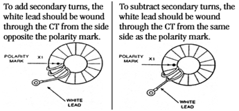
- To add secondary turns, the white lead should be wound through the CT from the side opposite the polarity mark.
- To subtract turns, the white lead should be wound through the CT from the same side as the polarity mark.
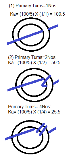
1) Modifications in Primary Turns Ratio of CT:
- The ratio of the current transformer can be modified by adding more primary turns to the transformer. By adding primary turns, the current required to maintain five amps on the secondary is reduced.
- Ka = Kn X (Nn/Na)
- Ka= Actual Turns Ration.
- Kn=Name Plate T/C Ratio.
- Nn=Name Plate Number of Primary Turns.
- Na=Actual Number of Primary Turns.
- Example: 100:5 Current Transformers.
2) Modifications in Secondary Turns Ratio of CT:
- Formula : Ip/Is = Ns/Np
- Ip = Primary Current , Is = Secondary Current , Np = No of Primary Turns, Ns = No of Secondary Turns
- Example: A 300:5 Current Transformer.
- The ratio of the current transformer can be modified by altering the number of secondary turns by forward or back winding the secondary lead through the window of the current transformer.
- By adding secondary turns, the same primary current will result in a decrease in secondary output. By subtracting secondary turns, the same primary current will result in greater secondary output.
- Again using the 300:5 example adding five secondary turns will require 325 amps on the primary to maintain the 5 amp secondary output or: 325 p / 5s = 65s / 1p
- Deducting 5 secondary turns will only require 275 amps on the primary to maintain the 5 amp secondary output or: 275p / 5s = 55s / 1p
- The above ratio modifications are achieved in the following manner:

- Current Transformer Ratio Modification:
|
CT Ratio |
Number of Primary Turns |
Modified Ratio |
|
100:5A |
2 |
50:5A |
|
200:5A |
2 |
100:5A |
|
300:5A |
2 |
150:5A |
|
100:5A |
3 |
33.3:5A |
|
200:5A |
3 |
66.6:5A |
|
300:5A |
3 |
100:5A |
|
100:5A |
4 |
25:5A |
|
200:5A |
4 |
50:5A |
|
300:5A |
4 |
75:5A |
- A primary turn is the number of times the primary conductor passes through the CT’s window. The main advantage of this ratio modification is you maintain the accuracy and burden capabilities of the higher ratio. The higher the primary rating the better the accuracy and burden rating.
- You can make smaller ratio modification adjustments by using additive or subtractive secondary turns.
- For example, if you have a CT with a ratio of 100:5A. By adding one additive secondary turn the ratio modification is 105:5A, by adding on subtractive secondary turn the ratio modification is 95:5A.
- Subtractive secondary turns are achieved by placing the “X1” lead through the window from the H1 side and out the H2 side. Additive secondary turns are achieved by placing the “X1” lead through the window from the H2 and out the H1 side.
- So, when there is only one primary turn each secondary turn modifies the primary rating by 5 amperes. If there is more than one primary turn each secondary turn value is changed (i.e. 5A divided by 2 primary turns = 2.5A).
- The following table illustrates the effects of different combination of primary and secondary turns:
|
CT RATIO 100:5A |
||
|
PRIMARY TURNS |
SECONDARY TURNS |
RATIO ADJUSTMENT |
|
1 |
-0- |
100:5A |
|
1 |
1+ |
105:5A |
|
1 |
1- |
95:5A |
|
2 |
-0- |
50:5A |
|
2 |
1+ |
52.5:5A |
|
2 |
2- |
45.0:5A |
|
3 |
-0- |
33.3:5A |
|
3 |
1+ |
34.97:5A |
|
3 |
1- |
31.63:5A |
Advantages of using a CT having 1A Secondary:
- The standard CT secondary current ratings are 1A & 5A,The selection is based on the lead burden used for connecting the CT to meters/Relays.5A CT can be used where Current Transformer & protective’s device are located within same Switchgear Panel.
- 1A CT is preferred if CT leads goes out of the Switchgear.
- For Example if CT is located in Switch Yard & CT leads have to be taken to relay panels located in control room which can be away.1A CT is preferred to reduce the load burden. For CT with very High lead length, CT with Secondary current rating of 0.5 Amp can be used.
- In large Generator Circuits, where primary rated current is of the order of few kilo-amperes only,5A CTs are used, 1A CTs are not preferred since the turns rations becomes very high & CT becomes unwieldy.
Danger with Current Transformer:
- When a CT secondary circuit is closed, current flows through it, which is an exact proportion of the primary current, regardless of the resistance of the burden. In the CT have a ratio of 1OOO/5A and to have 1OOOA flowing in the primary is carrying exactly 5A.
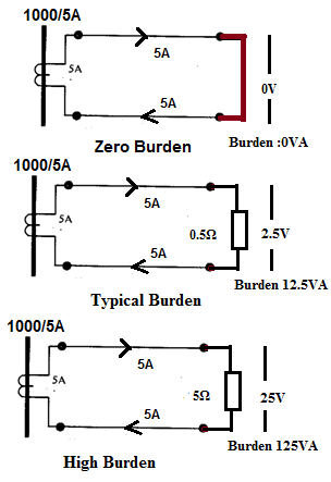
- If the secondary terminals S1 and S2 are short- circuited, there is no voltage between them.
- If now the short-circuit be replaced by a resistance of, say, 0.5 ohm the same 5A will flow through, causing a volt-drop of 2.5V and a burden of 5 x 2.5 = 12.5V A. If the resistance were increased to 5 ohms the terminal voltage with 5A flowing would rise to 25V and the burden to 125V A.
- The greater the resistance, the greater would be the voltage and burden until, as it approached infinity (the open-circuit condition), so also in theory would the voltage (and burden) become infinite. This cannot of course happen in practice because the CT would saturate or the terminals flash over due to the very high secondary voltage between them. But it does show the danger of open-circuiting the secondary of running CT. lethal voltages can be produced at the point of opening. This is why CT secondaries are never fused.
- The danger from an open-circuited CT is twofold. It can produce lethal voltages and so is a very real danger to personnel. The high voltage across the secondary winding could also cause insulation failure in that winding, leading at best to inaccuracy and at worst to burn- out or fire.
- Before ever an instrument or relay is removed from the secondary loop of a running CT (if such a thing had to be done), the wires feeding that instrument must first be securely short- circuited at a suitable terminal box or, better, at the CT itself. Similarly, if a running CT is ever to be taken out of circuit, it must first be firmly shorted. CTs with 1 A secondary’s are more dangerous than those with 5A, as the induced voltages are higher.
- Ammeter resistance is very low ,the current transformer normally works short circuited.
- If for any reason the ammeter is taken out of secondary winding then the secondary winding must be short circuited with the help of short circuit switch .
- If this is not done, then due to high m.m.f. will set up high flux in the core and it will produces excessive core loss which produce heat and high voltage across the secondary terminals
- Hence the secondary of current transformer is never left open
Sizing of CT for Building:
- New construction: size the CT to handle about 80% of the circuit breaker capacity. If the building is served by a 2000 amp breaker, use 1600 amp (2000 x 0.8) CT’s.
- Older buildings: the peak demand can generally be determined from the power company or from past billings. In this case add 20 to 30% to the peak demand and size the CT’s for this load. If the peak demand was 500 kW, the peak current on a 480/3/60 system would be 500,000 / (480 x 1.73 x 0.9 pf) = 669 amps. This assumes a 0.9 power factor. (Peak current would be higher with a lower power Factor.) Use CT’s about 20% larger. 800:5 CT’s would be a good selection.
- For older buildings with no demand history, size the CT’s the same as for new construction. Where possible, use multi-tap CT’s so that the ratio can be reduced if the maximum load is much less than 80% of the breaker size.
- CT’s that are used to monitor motor loads can be sized from the nameplate full load motor amps.


great and excellent topic
Nice and informative. Thank you very much. May your tribe increase.
Regards
SBV Rajesh.
Very very informative and comprehensive note on CTs
Many many thanks for this..
Do post more of this -may be on PTs
Regards
Manish
dear sir ,
i have a question , how i can decide the CT ratio in Ring Main Unit (HT Panel ) for protection of 630KVA Transformer and what are factors on bases CT Ratio can be calculated .
very easy understanding, useful and informative
thanks for your technical sharing
javad ahamed
Could you please send me more information about advantages and disadvantages of 1A CTs over 5A CTs and relative costs. Thanks
This is useful as well as informative. What I am looking for is ” is it possible to convert 5 amp to 1000 or 4000 amp through current transformer or through any transformer. Please write to me on nivedita.nivi@gmail.com.
By studying these data i learn new more things about ct”s and most of my doubts are clarified.Thank you very much.
How to calculate phase angle error for CT…Specification are 1:500 Turns ratio, 5A input current, 50 ohms purely resistive burden and 30 ohms winding DCR. Can anybody help this with formula….
while wiring CTs of transformer panel for metering circuit where should the CT wire be starred.. ie facing the bus or transformer side? Tell me for both import and export.. mail me in rrobinmathew@gmail.com
How to calculate the fault MVA in 66kV & 11kV side of two 66/11kV, 10MVA transformers with %Z =10.068 each for setting REF relay at both 66kV & 11kV sides. Let fault MVA at 66kV feeder be 1500MVA?
good discription on CT. Pl. give suggestion how to reduce ratio error and vk out in CT.
how to find out knee value of ct ratio 2500/5 VA 15 , CLASS=PX RCT(75 C)=.45 OHMS VK=105V
how can we calculate ct ratings ?its any formula ?
very good information.can you clear my doubt.
If i inject 100A current through P1 of CT primary,What is the angle i can expect in P2 side of primary.It will come same 0 degree or 180 shift.(not in secondary)please write me krishnappan2000@yahoo.co.in
What is the advantages of we metione p1 and p2
very very good one dear
GBY
Could you please send me more information about advantages and disadvantages of 1A CTs over 5A CTs and relative costs. Thanks
Great one.Thanks for the information
Very Good.
Could you send me information about how to calculate core’s ID,OD,Heights.
Please tell that just by measuring the winding resistance of the Secoundary of a CT is it possible to tell weather it is PS or 5P20 calss CT. if yes what is the theory of the same?
Thanks
Do you have any info of Zenox and tie-in resistors in LTC?
if ratio angle error is more,what will happen
can you tell me pls:
With a 300/5 CT ratio, how much is the secondary current if we inject 180 A into primary windingsWhat is the ratio of a 1A current transformer if there is 450 amps are flowing in the primary winding?
Not getting Point !!!
Normally CT Ratio is 300/5=60 if your inject current is 180A than your current in CT primary side is 180/(300/5)=3A
what happens if 600A is applied to 300/5A ct
Thank u very much Jignesh Sir. Your’s notes on CT is really useful for my project work for selection of CT.
i want learn all type of current transformer (b.p.l/cbct) . if some coaching available pls tell.
sir can u tell me more about yard CT and ohm CT.
Respected Sir, How to Test BURDEN of CT ( Ratio-60/5,VA-10,Cl-1).
RajeshKumar
Dear Mr. PARMAR
Such a good information, thanks for sharing the knowledge.
Regards
Abhijit
Dear Jignesh.Parmar,
Please help me, how to reduce Phase angle error in current transformer.. and please tel me the formula for calculating phase angle error in current transformer..
why multiple taps required on primary of CT, like 220kV, 2000-1000/1-1-1A? wht is the reason behind this?
sir i want worked examples of metering core current transformer
Dear Sir , thank you for the good Information.
i have some Problem.
i use the CT 200:5 and my kwh meter is 5 A, but i get Differences occur measurement results with the results of calculations about 30%, maybe you can help me provide information
Thanks a lot Sir.
Just what I needed. Perfect! and thanks!
what should be knee point voltage of primary current transformer as the above calculation is secondry current transformer.
sir why we short the Ct seconary terminals
Hello sir…
It’s is such a usefull article…
But sir, can u plz tell me, exactly what is Insrument Security Factor…???
In details…
And how to it is used in design calculations of current transformer…???
hi sir can you please tell me if you can connect a kw/h meter and a ammeter on the same ct and if you can how much must the va be
excellent piece of information. i tried many books but couldn’t find the information the way i wanted but here every thing is available for CT’s. thanks parth
HI jignesh. can you please post anything on your blog which shows how to select CT ratio for earth fault and sensitive earth fault protection from a single line diagram???
Dear Mr.Jignesh,
Thanx for a very useful information about CTs
K.Sri Rama Prasad, IBTPLtd,Tuticorin, T.N
Jignesh,
Information Known:
300 MVA Transmission Line
CT Ratio 2000/5
Voltage – 138kV
What CT ratio would I pick for my protective relays?
Thanks,
thanks for the valid info
Hi,
Can you tell me importants of star points of secondary and its earthing.
And please tell why we short/earth some time S1 or some time S2 of all phase
good information provided for me
very good
thanx for the usefull information…
SIR,
I read on CTs but Iwant to know about meggering of a CTprimaryor secondary. what happens if we megger a CT
Hello sir, I am looking for core design formula of ct and pt. May you please help me.
thanks for information.
what is difference between multicore and multi ratio ?
very valuable preliminary information
.
Nice artical it cover most of topics regarding ct
how can a same ratio CTs have different value of resistance
Very nice article. I have a question , What will be accuracy of protection CT in metering zone. Many panel ammeters are connected to secondary of protection CT.
very very informative article. thank you so much..
how to calculate I.S.F.?
can tell me about accuracy class 1.0 and 3.
Really useful Article… Thanks
I want to know more about Current transformer at metering side.(CT used inside panel meters). what are major difference between external CT & metering CT? Design considerations?etc.
Current Transformer has primary 1 turn and secondary side multiple turns.
What will happen if voltage is applied on secondary side of the CT, If primary has only 1 number of turn. will it induce current in primary? any formula? example?
Once again thanks for topic
Can CT have dual accuracy? I have a 138kV circuit breaker with a bushing CT class” C800 & 0.3B1.8″
please help me find the short circuit current for 11KV and 33KV current transformer
Very nice information Jagdish. Please help for my following two issues.
1. Can I use 50:5 CT in place of 10:1 CT for core balance? What is key difference between two ? 2. In our all 4 kV panels we have ammeters coonected on secondary of protection CT. What is accuracy of protection CT in metering zone? Any rough Idea.
how current direction is defined in CT
Please tu peux comprendre comment calculer le courant du TC
very good sir,
thanks a lot.
your ct leacture is good for maintenance engg&purchase tks sir
Nice and useful information. Thank you very much.
If it is possible to connect 2 CTs parallel (S1 into S1) and then to the power analyzer,to measure a shared load of two sides of a common busbar set…?,
thank you very much sir
how to find minimum current energised in the CT.
Dear Parmar : we are indebted to you for the information you have collected and made available to us
Dear Sir,
Please tell me there is one one customer is required PF test terminal in case of CT, what is the meaning for the same. It is applicable in oilcooled CTs?
Dear Sir, kindly clarify in simple lay man terms.
Current through CT meter via Transformer from the main lines.
I have a current transformer with 1 main meter outside the building and a control panel having 5 CT meters with black round coils inside the building. I want to know, A) when current pass through the Transformers, will the current be reduced or be the same and after that B) when current pass through the CT meters with black round coils, will the current be reduced or be the same. C) in the above process will the reading of the main meter be same or different, from the total reading of all the 5 CT meters.
Dear sir, kindly clarify is simple layman words,
Current through CT meter via Transformer from the main lines.
I have a current transformer with 1 main meter outside the building and a control panel having 5 CT meters with black round coils inside the building. I want to know, A) when current pass through the Transformers, will the current be reduced or be the same and after that B) when current pass through the CT meters with black round coils, will the current be reduced or be the same. C) in the above process will the reading of the main meter be same or different, from the total reading of all the 5 CT meters.
Please help, I need to install 100A CT KWH meter, so which size of the CT i need to use?
Shared good knowledge about basics of CTs. Thank you and request you to please share some knowledge about stress shield connection oh high rating window type CT
How to decide the shorting neutral point in CT secondaries for differential protection?
vvvvvv good
Sir can you provide such a useful and comprehensive information about PT ? I could’t found such article in this website.
Dear Sir,
This is very informative and useful information of CT.Thank u so much. It clears my all confusion about CT.
Dear Jignesh.Parmar,
Please help me, how to reduce Phase angle error in current transformer.. and please tel me the formula for calculating phase angle error in current transformer..
Dear Shri Parmar Ji
Excellent information on CT. Thank you very much.
Dear sir, can we have core 1 rated output 1A and core 2 rated output 5A of same CT?
Dear Mr. Parmar,
Thanks for your very good explanation of current transformer theory.
I have an technical inquiry related to field testing of multi ratio current tranformers.
A couple of weeks ago I performed turns ratio tests to a 2000:5, 230kV inductive current transformer. The results of the tests were a Little strange, since the results of test of the secondary tap ends (X1-X5 corresponding to 2000:5) were satisfactory, but at the same time, I did get very high deviations after testing some of the middle taps of the secondary winding. For instance, taps corresponding to 800:5 or 600:0, provided deviations above 70% from nominal ratio.
Could you provide some comments about the posible reasons for the results obtained on these tests.
great
Very helpful article with each bit of basics….
very good
this is awesome. very well explained. thank you
Dear Mr. Jignesh and all other experienced guys
Please explain if a low voltage CT can be used on a 13.8KV or 15KV insulated cable,
please give some electrical standard references too.
dear sir can we connect 1 amp meter with CT if CT ratio of 100/5
no it is undersized meter the CT ratio of 100:5 therefore the maximum is 5A not 1 A.
Thanks for knowledge contribution
Dear Sir,
I would like to know, is it possible in any circumstance to connect 3P4W, HT, 0.2s meter with 0.5s class CT with secondary 5A?? Will the accuracy be within limits? Please let me know sir
Plz send tha toroidal core metering and other ct formulas .
Dear jignesh sir, i want to contact you . please give me your contact no
Thank you its great and helpful article with each bit of basics
Dear Jignesh sir your content is very brief and informative, can you post some material on CT sizing for TPY class CT as well.
Thanks
Great full information.
can i get the complete calculation for composite error of the Current and Voltage Transformer. please give me.
The current transformers are of great use to measure the line current special transformers. They are of great use these days. Thanks for explaining in brief about them and their types!!
good
What is the significance of S in 0.2s metering current transformers and what is the necessity of this type of CT’s.
What is meant by “S” in 0.2s metering C.T’s
Dear Sir,
Can you tell me how can I calculate the FS and ALF for a current transformer, if I know: Rct at 75 degree, Uknee and Iknee ?
why does magnetizing reactance (Xm) of CT become zero during saturation of CT core?
I am interested in current monitoring using a CT. Request if you can help me find the correct CT with Core and windings to monitor 220V mains line and the output needs to fed to an Arduino board. I understand this requires safety issues die to high secondary winding and voltage. Also the voltage needs to be regulated to bring it to DC 0 to 5 V level for my project. Can you please help me?
How to select the CT Size. Primary side 11kv supply with 750 KVA Transformer .
Sir, if the primary current of ct (300/5) exceeds 300 A, what will happen(with burden within range of ct)?
It will show the reading in ammeter or not?
Dear sir
Thanks for sharing your technical expertization. I have a question, sir how can we decide area of core for metering (nano crystal / m3, zdkh) or protection (crgo, m4) for any given burden and ratio.
Regards
Er. Imran
Sir,
how can we differentiate protective ct from measuring ct by simply looking at both.
and CB connected after it operates at primary or secondary current of protective CT.
thanks for useful information , people like you are still needed in engineering perspective as asset to share their knowledge using this platform and i learned a lot from this informatoin.
sir,if CT is feeding a metering ckt we better to have which option sir
A. higher safety factor (FS)value
B. lower safety factor (FS)value
C. No effect
D. safety factor (FS) depends on CT ratio
pls answer sir
Just i can say is THANK YOU Sir.
Well explained
Sir,
how can measure current in Y phase by using CT in R & B phase only
what is difference between ct ratio 400/5+5 and 400/5-5???
thank you very much sir…
I enjoyed reading the comments more than the article hahaha! Great read though.
Explain to find out the protection of ACB breaker from formula i.e OverCurrent/UnderVoltage/Short Circuit/Earth Fault/Instantaneous.
Please send me the formula by which all these parameter find out.
regard
Prateek Shukla
i want to implement proposed solution of mal functioning of Differential relay.
.
can u help me by providing circuit diagram how a source(220AC) and then step up and step down transformers and CT and PT and Load and arduino and relay connected for project …
looking kind response
what happens when i apply more than 500 v on Secondary of Current transformer
Sir i have 4 ampere variac which is handling volatages through wire which is going to connect with Heater (100W). I want to use CT type Ammeter (0-5 ampere range) in between Variac and Heater in series. I am not from electrical background, I am confused in which type of Current transformer i have to use and what about the turn ratio and all that????? Plese help me Sir….
How to find the electromagnetic force created by rated dynamic current in current
transformer
CAN ANYONE GIVE ME AN IDEA ABOUT 11 KV SDT OR LOADSHADING TRANSFORMER WHICH HAVE ONLY HV WINDING AND TWO LEG CORE.
Can you please advise for 66kV statistical metering if CT has 0.2 class, VTs have 0.5M class. Will this be ok or do we require 0.2 class for the VTs to comply with metering parameters.
kindly let me know ? what does it mean 100/5 = 10 here the multiplying factor is 10 instead of 20 ? what will me my multiplying factor ?
Good morning everyone. I have a GE multilin 239 motor protection relay and one of the features is to protect the motor above 75A. meaning this relay is designed for high current motor protection. The secondary current has two option 5A or 1A meaning the maximum current going to the 239 relay is just 5A. if the F.L.A of a motor is 75 amperes and the CT ratio is 75:5 normally we will use CT to step down the current from 75A to 5 A. What about if I have a motor which has a very low F.L.A of 2A. do I need to use CT to step down the current or should I connect it directly to the 239 relay using the 5A maximum? please answer it because I have a debate here with my colleagues they said it is still needed but in my opinion the F.L.A. of 2A does not need CT anymore since I have an option to choose the 5A maximum but if the FLA is more than 5A that’s the time I have to use CT because the maximum is only 5 amperes.
Thanks
Hallo,
do you know a Formula for secondary CT resistance estimation? Thank You
Measuring CT ratio 200 :1 & Energy Meter is 5 Amps if connect this any problem
Can be connected by accuracy will be different
How can we combine the effect of two different CT installed at two differeny source so as to get desired output.
Very nice
Thanks a lot sir
for sharing this essential knowledge.
Good information’s thanks
Hi. am looking for current electrical ct wiring diagram, with ratio 400/5 10VA, IEC 44-1, BS 7626, class 10p10. as soon as possible. your help will highly be appreciated thanx.
Thabiso @ Sedibeng Transformers
Sir,what is the difference in the functioning of Round CT & Square CT?
more explanation about :
power flow direction (P1,P2)
Terminal (secondary winding) identification (S1,S2,….)
Sub: short time rating test on CT with Multitap on secondary side.
I have a CT 100-50/1A Low Voltage window type metering CT with s1-s2 50 turns and s2-s3 with 50 turns for accuracy of clas 0.5
which needs to be tested for 25 Ka for 3 secs.
Regarding connection on the secondary, the standards say that the seconday winding(s) should be short circuited. In this particular case:
a.) Are only s1-s3 terminals to be shorted or ( keeping s2 not shorted with s1 and s2)
b.) All s1, s2 and s3 are to be shorted.
Assuming that the core size used is very large and the core does not saturate at both 50/1 or 100/1a, would like to know the current value in both the cases.
For case a, it is evident that current in secondary will be 25000/100=250A. For case b, am confused whether current is s1-s2 portion of the winding will be 25000/50=500a or 250a as in case a above.
Would appreciate response and also the interpretation of the standards.
Excellent Man !! Keep it up.
Impeccably Excellent
If I had a 5p20 CT which accuracy class C class or T class should i select for testing it
hi,
how we can increase knee point voltage of current transformer?
thanks for helping.
Nice work
Dear Sir,
When we calculate the burden for the CT as you said we will be adding the VA burden of its loads, such as ammeter etc. The VA of those loads will be different or same for 1A CT and 5A CT ?
very good write up.
please I want more lite on MF on CT And PT
Hi Sir, how can I make a calculation to see the relationship between SF and ammeter’s overloading?
How can I make sure my ammeter is protected during high short circuit current if my ammeter’s overloading is 10 X In for 1s.
Very nice technical article, covering almost all about Current Transformer.
Sir please share the knee point voltage calculation for class-PS CT in excel format.
For very low primary currents at low loads(when CT ratio is high when compared to load current), how to estimate the exact percentage error for accuracy measurement of energy
I’ve never seen the CT details like this. I’ve one question. Lead wire burden considers factor of 1.2 for 3 phase 4 wire CT connection. Could you explain the theoritical reason, or basis?